Steel pipe seam joining and welding integrated machine

An all-in-one machine and welding mechanism technology, applied in welding equipment, auxiliary welding equipment, welding/cutting auxiliary equipment, etc., can solve the problems of difficult to guarantee the structural strength of steel pipes, uneven width of steel pipe welds, and difficult to guarantee welding accuracy, etc. The effect of keeping the gap width stable, the welding seam width uniform, and reducing the difficulty of welding

Pending Publication Date: 2018-01-05
ZHEJIANG NINGYUAN COUNTY TOWER MAST MAKE
View PDF0 Cites 7 Cited by
  • Summary
  • Abstract
  • Description
  • Claims
  • Application Information

AI Technical Summary

Problems solved by technology

[0004] Due to the heavy weight of the large-diameter steel pipe, the steel pipe is composed of two semi-circular steel pipe sheets welded together. Affected by its own structure and weight, in order to ensure the structural strength of the overall steel pipe, a large space needs to be reserved between the two steel pipe sheets. The gap is used to fill the welding liquid to form the weld, and the above-mentioned technical solution only fixes the left and right sides of the steel pipe sheet through the left pressure roller assembly and the right pressure roller assembly. In order to improve the stability of the steel pipe, the left Both the side pressure roller assembly and the right pressure roller assembly have a certain contact force on the surface of the steel pipe (by controlling the distance between the left pressure roller assembly, the right pressure roller assembly and the steel pipe), but it cannot make the left pressure roller The component and the right pressure roller component are too close to the steel pipe, which may easily cause the gap to be welded to be too narrow or even closed. Therefore, the above technical solution has great welding difficulty, which reduces the welding efficiency, and the weld seam width of the steel pipe after welding is uneven. Phenomenon, the welding accuracy is difficult to guarantee and the structural strength of the steel pipe is also difficult to guarantee, and there are deficiencies in improvement

Method used


Image

  • Steel pipe seam joining and welding integrated machine
  • Steel pipe seam joining and welding integrated machine
  • Steel pipe seam joining and welding integrated machine

Examples


Embodiment Construction

[0045] refer to Figure 1 to Figure 14 The embodiments of the present invention will be further described.

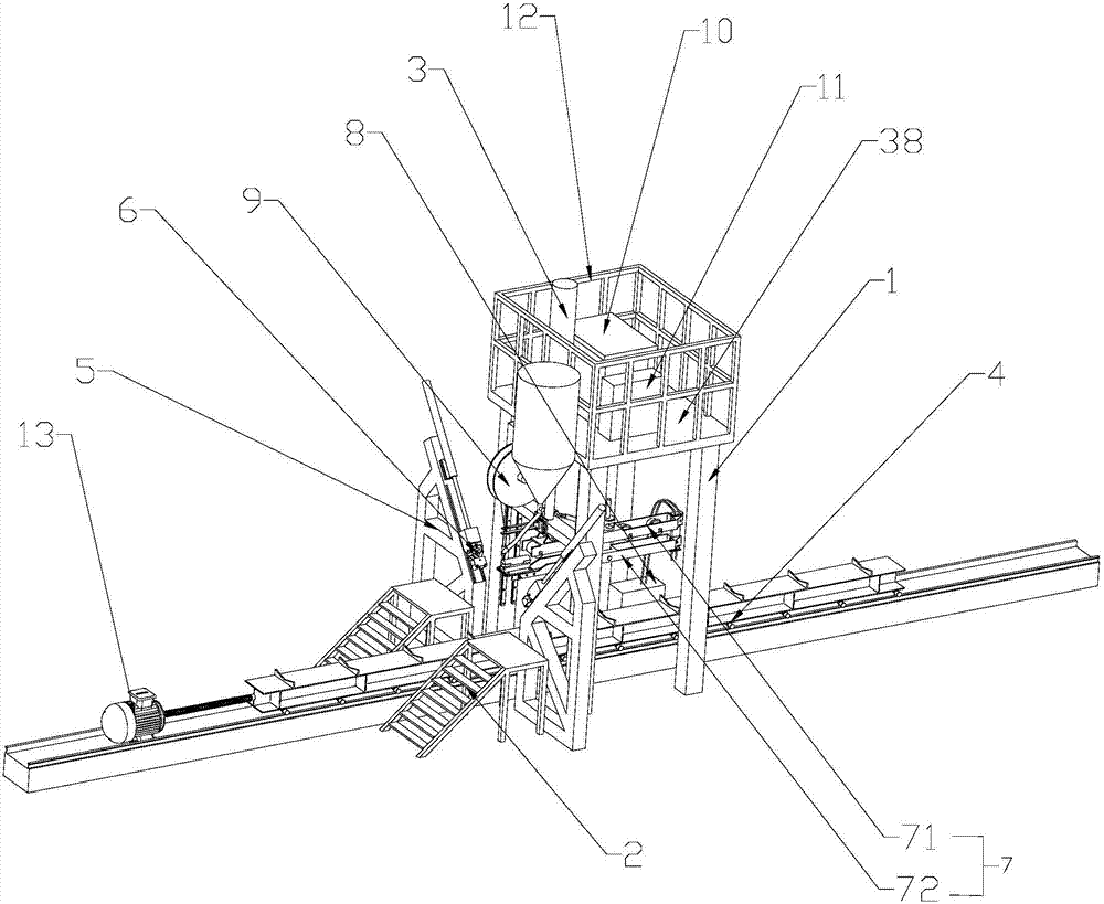
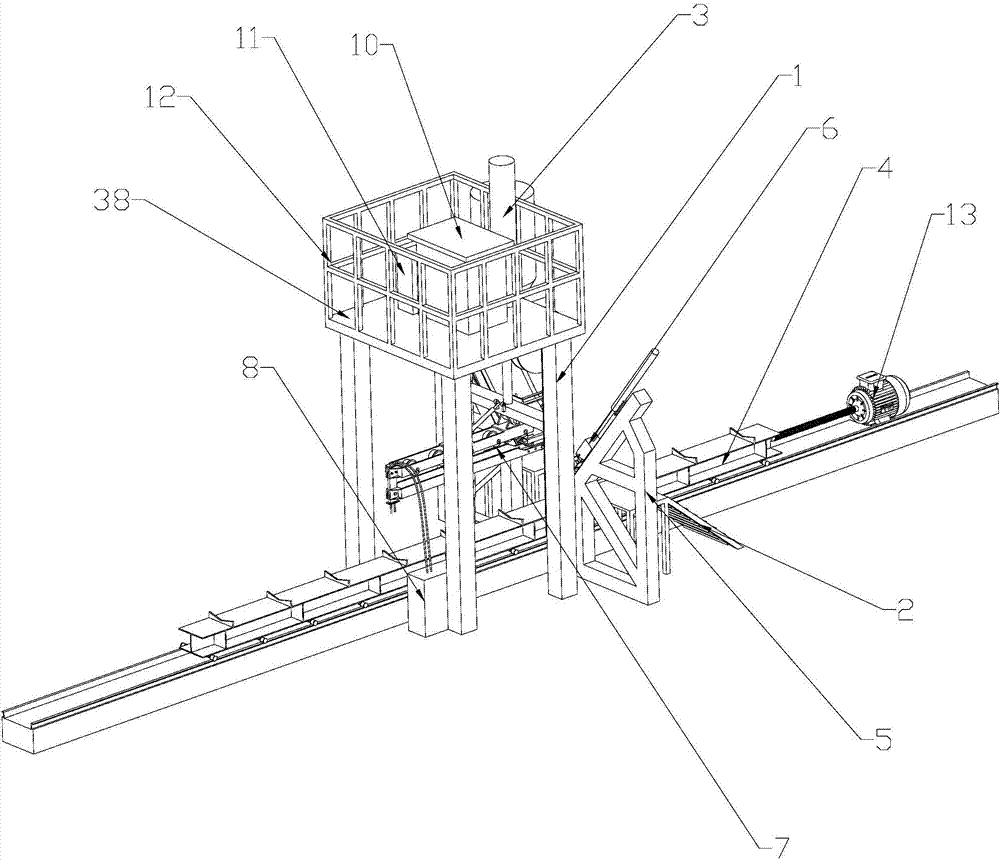
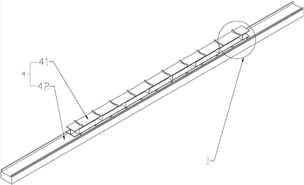
[0046] Such as Figure 1 to Figure 2 As shown, a steel pipe seam welding machine includes a main frame 1, the main frame 1 is a cuboid structure, the main frame 1 is welded by several square steels, and a steel pipe for transporting steel pipes to be welded is installed under the main frame 1. The conveying device 4, the main frame 1 is the rear side and the front side in sequence along the steel pipe conveying direction, and the steel pipe conveying direction is as follows figure 1 In the direction shown by the arrow, the front side of the main frame 1 is connected with the welding mechanism 9 and the main oil cylinder 3, and there are two side frames 5 placed on the front side of the main frame 1. The side frames 5 are respectively located on the left and right sides of the steel pipe. On the side frame 5 The pressure roller assembly 6 used to fix the left and right...


PUM


Abstract

The invention discloses a steel pipe seam welding integrated machine, which comprises a main frame, a main oil cylinder connected to the main frame and arranged vertically, a welding mechanism connected to the main frame and located above the steel pipe, and located below the main frame for transporting The conveying device for welded steel pipes, the side frames located on the left and right sides of the steel pipes, the side frames are connected with pressure roller assemblies for fixing the left and right sides of the steel pipes, the steel pipe seam welding machine is equipped with a bracket group, and the bracket group Cards and pieces are set inside to keep the gap between the steel pipes constant, which reduces the difficulty of welding, improves the welding efficiency, and keeps the weld width of the steel pipe after welding uniform, thus ensuring the structural strength of the steel pipe.

Description

technical field [0001] The present invention relates to a steel pipe processing machine, more specifically, it relates to a steel pipe seam welding integrated machine. Background technique [0002] The steel pipe seaming machine is one of the key equipment of the large-diameter straight seam welded pipe production line. The existing common steel pipe seaming machine uses a hydraulic cylinder to abut against the weld above the steel pipe and clamping hydraulic cylinders on both sides to abut the steel pipe. Fixed, so as to carry out seam welding of steel pipes. [0003] The patent document with the application number 2015108005614 discloses a straight seam steel pipe seaming machine, including an upper beam, a column, a lower beam, an upper guide assembly, an upper pressure roller assembly, an upper left inclined side pressure roller assembly, an upper right inclined side pressure roller assembly, The rotating roller frame, the left pressure roller assembly, the right pressu...

Claims


Application Information

Patent Timeline
Patent Type & Authority Applications(China)
IPC IPC(8): B23K37/02B23K37/053B23K101/10
Inventor 邱裕忠王新聚杜文甫
Owner ZHEJIANG NINGYUAN COUNTY TOWER MAST MAKE
Why Eureka
Try Eureka