Base structure of electrolysis device for separation of hydrogen and oxygen and electrolysis device with the base

An electrolysis device and electrolysis electrode technology, applied in electrolysis components, electrolysis process, chemical instruments and methods, etc., can solve the problems of no waste water and waste gas separation, waste water fouling and odor, waste water treatment, etc., to ensure practicality and stability. properties, ensuring concentration and effectiveness

Active Publication Date: 2019-04-23
FUZHOU PINXING TECH DEV
View PDF7 Cites 0 Cited by
  • Summary
  • Abstract
  • Description
  • Claims
  • Application Information

AI Technical Summary

Problems solved by technology

This technical solution adopts the hydrogen structure of hydrogen and oxygen separation system to realize the separation of hydrogen and oxygen, but there is no related pressure relief valve in the vacuum cup body and cup cover to solve the problem of increasing the internal pressure of the container; at the same time, although the technical solution is in The bottom of the anode chamber is provided with an exhaust and non-drainage channel, and the purpose of exhaust and non-drainage is achieved by setting a breathable film on the channel, but the waste water and waste gas are not separated, and the waste water in the anode chamber is accumulated in the electrolytic chamber. Effective treatment of the waste water in the room will cause the waste water inside the hydrogen-rich water cup to silt and stink over time.

Method used


Image

  • Base structure of electrolysis device for separation of hydrogen and oxygen and electrolysis device with the base
  • Base structure of electrolysis device for separation of hydrogen and oxygen and electrolysis device with the base
  • Base structure of electrolysis device for separation of hydrogen and oxygen and electrolysis device with the base

Examples


Embodiment Construction

[0035] Below in conjunction with accompanying drawing and specific embodiment the present invention is described in further detail:

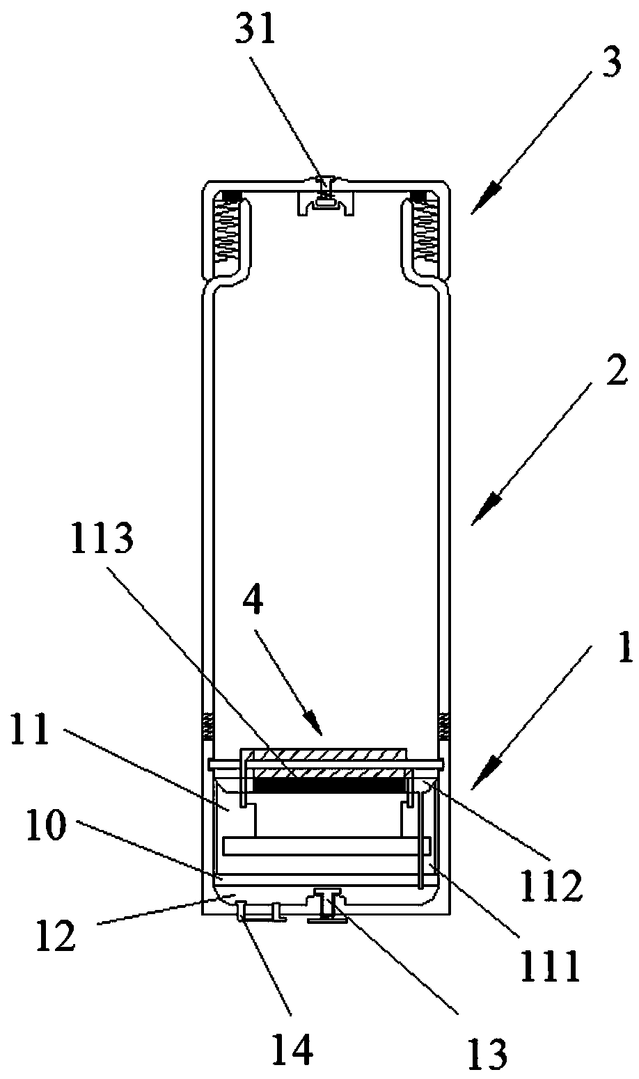
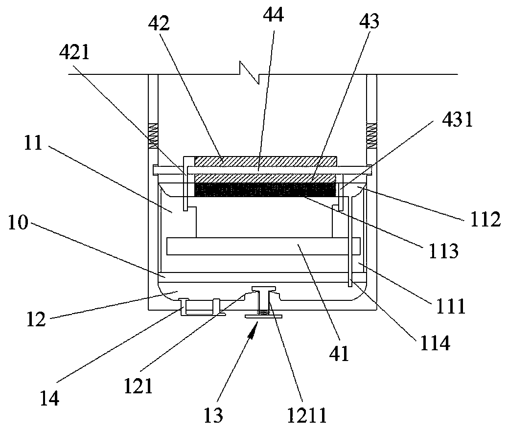
[0036] see Figure 1 to Figure 4 , an electrolysis device, including a seat body 1, a main body 2 and a cover body 3 connected in sequence; specifically, the seat body 1 is arranged below the main body 2 and the upper part of the seat body 1 and the lower part of the main body 2 are connected by thread sealing, so The cover 3 is arranged above the main body 2 and the cover 3 is connected with the upper part of the main body 2 through thread sealing; the base 1, the main body 2 and the cover 3 together form a container for holding water.

[0037] The seat body 1 includes a shell, which is divided into an upper electrolysis chamber 11 and a lower waste water and waste gas chamber 12 by an isolating device 10 arranged at the lower part of the seat body 1. In this embodiment, the isolating device 10 is a fixed Sealing is connected to the isolation ...


PUM


Abstract

The present invention relates to a seat body structure of an electrolysis device for separating hydrogen and oxygen and an electrolysis device with the seat body. The seat body structure includes a housing, an electrode tank and an electrolysis electrode are arranged in the housing, and liquid adsorbents are contained in the electrode tank. The liquid adsorbent is adsorbed with water used for preliminary electrolysis of the electrolysis electrode; the bottom of the electrode tank is provided with an opening, and the electrolysis electrode includes a cathode sheet, an anode sheet, and a gas / water separation film closely arranged between the cathode sheet and the anode sheet, and the gas The water / water isolation membrane is clamped on the inner wall of the housing above the electrode tank. The gas / water isolation membrane has the characteristics of passing water and not ventilating when the electrolysis electrode is electrolyzed, and not passing water and not ventilating when the electrolysis electrode is non-electrolyzed; the anode piece is close to the liquid adsorbent The bottom of the casing is provided with a gas-water separation and discharge device for separating the waste water and waste gas generated on the anode sheet side of the electrolysis electrode and then discharging them to the outside of the casing. The device can fully ensure the airtightness of the structure or device, and can automatically control the air pressure inside the device.

Description

technical field [0001] The invention relates to the technical field of hydrogen-rich water cups, in particular to a base structure of an electrolysis device for hydrogen-oxygen separation and an electrolysis device with the base. Background technique [0002] The process of electrolyzing water is actually the process of converting liquid substances into gaseous substances, and the obtained products include hydrogen, oxygen, ozone, chlorine and so on. At present, hydrogen production by electrolysis of water mainly includes the hydrogen structure of hydrogen-oxygen mixture and the hydrogen structure of hydrogen-oxygen separation. [0003] The hydrogen structure of the hydrogen-oxygen mixture is not suitable for the design of direct drinking water because the anode by-product components such as ozone, high-valent chlorine compounds, and chlorine are harmful to the human body; the hydrogen structure of the hydrogen-oxygen separation system can convert the product of the cathode ...

Claims


Application Information

Patent Timeline
Patent Type & Authority Patents(China)
IPC IPC(8): C25B9/08C25B1/10C25B9/19
CPCC02F1/461Y02E60/36C25B1/04C25B9/73C25B9/19
Inventor 周陈兴蔡婷婷
Owner FUZHOU PINXING TECH DEV
Why Eureka
Try Eureka