Hot swap circuit, interface circuit and electronic equipment

A hot-swappable technology for electronic equipment, which is applied in the field of hot-swappable circuits, interface circuits and electronic equipment, can solve the problems of devices and X-ray flat panel detectors in the burnt-out stage circuit that cannot work normally, so as to reduce the risk of use, Easy to achieve, simple structure effect

Inactive Publication Date: 2018-01-05
IRAY IMAGE TECH TAICANG CO LTD
View PDF4 Cites 5 Cited by
  • Summary
  • Abstract
  • Description
  • Claims
  • Application Information

AI Technical Summary

Problems solved by technology

[0006] In view of the shortcomings of the prior art described above, the purpose of the present invention is to provide a hot-swappable circuit, interface circuit and electronic equipment, which are used to solve the problem of the existing X-ray flat panel detector being burned in the subsequent circuit during the hot-swapping process. device, causing the problem that the X-ray flat panel detector cannot work normally

Method used


Image

  • Hot swap circuit, interface circuit and electronic equipment
  • Hot swap circuit, interface circuit and electronic equipment

Examples


Embodiment 1

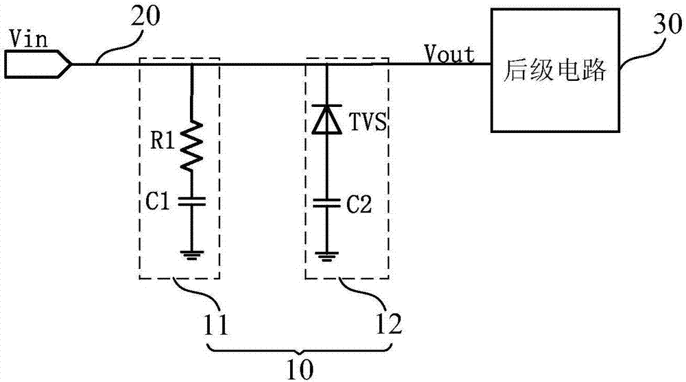
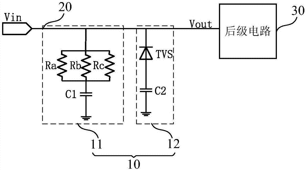
[0036] Such as figure 1 with figure 2 As shown, this embodiment provides a hot-swap circuit, and the hot-swap circuit includes:

[0037] The first-level protection unit 11 is used to consume and absorb the transient high-voltage spikes generated at the moment of hot plugging; and

[0038] The second-level protection unit 12 is connected in parallel with the first-level protection unit 11, and is used for consuming and absorbing the remaining transient high-voltage spike pulse after being consumed and absorbed by the first-level protection unit is greater than a preset voltage. Clamp the voltage across it while capturing the remaining transient high voltage spikes.

[0039] As an example, such as figure 1 As shown, the first-level protection unit 11 includes a first resistor R1, one end of the first resistor R1 is connected to the second-level protection unit 12, and the other end of the first resistor R1 is connected to the first capacitor C1 One end of the first capacito...

Embodiment 2

[0055] Such as figure 1 with figure 2 As shown, this embodiment provides an interface circuit, the interface circuit includes a power input interface line 20, and the hot swap circuit 10 connected in parallel to the power input interface line 20 as described in the first embodiment above.

Embodiment 3

[0057] Such as figure 1 with figure 2 As shown, this embodiment provides an electronic device, and the electronic device includes the interface circuit as described in Embodiment 2, and a post-stage circuit 30 connected to the interface circuit.

[0058] Preferably, in this embodiment, the electronic device includes an X-ray flat panel detector.

[0059] see below figure 1 with figure 2 The working process of the hot swap circuit is described in detail.

[0060] When the external power line plug is inserted into the power interface of the X-ray flat panel detector, the power input interface line 20 generates a transient high-voltage spike at the moment of power-on. At this time, the The first resistor R1 consumes part of the voltage energy of the transient high-voltage spike, and the first capacitor C1 absorbs part of the voltage energy of the transient high-voltage spike and releases it through the ground; when passing through the first-level protection unit When the r...


PUM


Abstract

The present invention provides a hot-swappable circuit, an interface circuit, and electronic equipment. The hot-swappable circuit includes: a first-level protection unit for consuming and absorbing transient high-voltage spikes generated at the moment of hot-swapping; and a second A first-level protection unit, connected in parallel with the first-level protection unit, used to consume and absorb the remaining transient high-voltage spikes when the remaining transient high-voltage spikes consumed and absorbed by the first-level protection unit are greater than a preset voltage At the same time as the spike pulse, the voltage across it is clamped. Through the hot-swappable circuit, interface circuit and electronic equipment of the present invention, the problem that the existing X-ray flat panel detector burns the devices in the subsequent circuit during the hot-swappable process is solved, causing the X-ray flat panel detector to fail to work normally question.

Description

technical field [0001] The invention belongs to the field of X-ray flat panel detectors, in particular to a hot-swappable circuit, an interface circuit and electronic equipment. Background technique [0002] X-ray detectors have experienced a century of development, from the traditional film type to today's digital type, which has experienced CR detectors, CCD X-ray detectors, CCD splicing X-ray detectors and the most mainstream at present. X-ray flat panel detector. X-ray flat panel detectors can capture X-rays and convert the X-ray images of the measured objects into digital images for easy viewing, analysis, storage and dissemination. They are widely used in medical, biological, material and industrial testing and other fields. [0003] X-ray flat-panel detectors can be divided into two types: direct imaging and indirect imaging. The direct imaging detector directly converts X-rays into electrical signals, while the structure of the indirect imaging detector consists of ...

Claims


Application Information

Patent Timeline
Patent Type & Authority Applications(China)
IPC IPC(8): H02H9/04
Inventor 姜婷尤超勤马扬喜
Owner IRAY IMAGE TECH TAICANG CO LTD
Why Eureka
Try Eureka