Electric vehicle solar energy charging system and application method thereof in stereo garage

A charging system and electric vehicle technology, applied in the field of power supply, can solve the problems of inability to complete the charging requirements of electric vehicles, lack of charging system, and consume a lot of human and financial resources, and achieve the effects of reducing pollutant emissions, simple wiring, and low cost

Pending Publication Date: 2018-01-05
北京欧力联合机械技术研究院
View PDF0 Cites 1 Cited by
  • Summary
  • Abstract
  • Description
  • Claims
  • Application Information

AI Technical Summary

Problems solved by technology

[0002] With the development and progress of new energy vehicle technology, especially new energy vehicles that do not consume gasoline, produce no pollution, and save resources, they have been promoted and applied in more and more cities, and have also been welcomed by a large number of car users, especially electric vehicles. Driven by the national preferential policies, it has been widely accepted by a large number of car users. Electric vehicles need to be charged when they are in use, so they need special charging piles. The existing technology generally uses mains electricity to connect charging piles. To complete the installation of the charging piles with the technical staff of the State Grid, the mains power supply consumes a lot of manpower and financial resources. As for the mains itself, since most of the northern regions use coal-fired power generation, the use of mains power charging has not been fully realized. The goal of reducing pollution and improving air quality. At the same time, the existing three-dimensional garage itself does not have a charging system and cannot meet the charging needs of electric vehicles.

Method used


Image

  • Electric vehicle solar energy charging system and application method thereof in stereo garage
  • Electric vehicle solar energy charging system and application method thereof in stereo garage
  • Electric vehicle solar energy charging system and application method thereof in stereo garage

Examples


Embodiment Construction

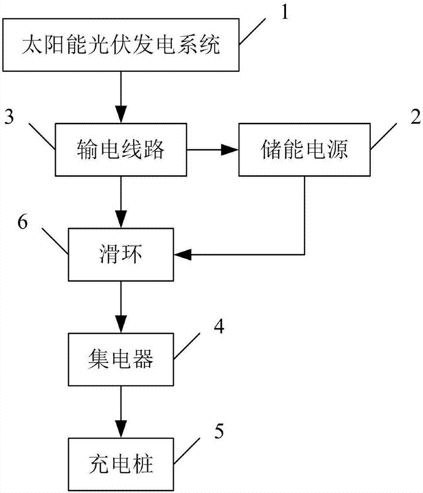
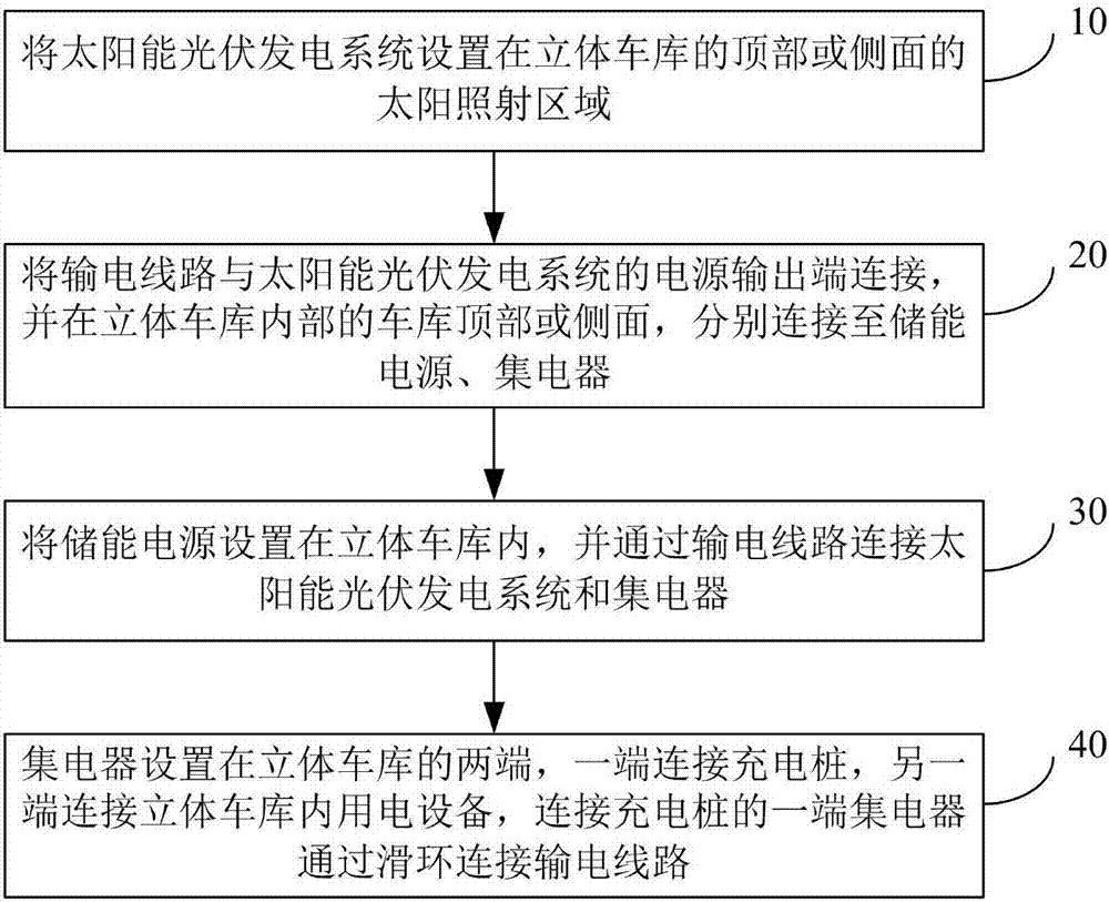
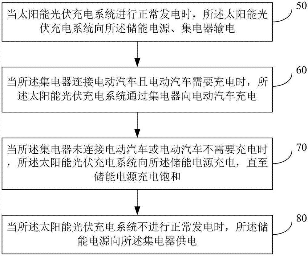
[0035] Various exemplary embodiments of the present invention will now be described in detail with reference to the accompanying drawings. It should be noted that the relative arrangements of components and steps, numerical expressions and numerical values ​​set forth in these embodiments do not limit the scope of the present invention unless specifically stated otherwise.

[0036] At the same time, it should be understood that, for the convenience of description, the sizes of the various parts shown in the drawings are not drawn according to the actual proportional relationship.

[0037] The following description of at least one exemplary embodiment is merely illustrative in nature and in no way taken as limiting the invention, its application or uses.

[0038] Techniques and devices known to those of ordinary skill in the relevant art may not be discussed in detail, but where appropriate, such techniques and devices should be considered part of the description.

[0039] It ...


PUM


Abstract

The invention discloses an electric vehicle solar energy charging system and an application method thereof in a stereo garage. The system comprises a solar photovoltaic power generation system, an energy storage power source, a power transmission circuit, a current collector and a charging pile; the solar photovoltaic power generation system is connected with the energy storage power source and the current collector through the power transmission circuit; the energy storage power source is connected with the current collector through the power transmission circuit; the current collector is connected with the charging pile through the power transmission line. An electric vehicle and the stereo garage are powered through the solar photovoltaic charging system, the purposes of lowering pollutant discharge and achieving environmental protection are achieved, and compared with municipal administration power consumption, the cost of solar photovoltaic charging is lower; by adopting the combined design of the current collector and a slip ring, wiring becomes easier, and the problem that the power transmission line is twined is avoided.

Description

technical field [0001] The invention relates to the technical field of power supplies, in particular to a solar charging system for an electric vehicle and its application method in a three-dimensional garage. Background technique [0002] With the development and progress of new energy vehicle technology, especially new energy vehicles that do not consume gasoline, produce no pollution, and save resources, they have been promoted and applied in more and more cities, and have also been welcomed by a large number of car users, especially electric vehicles. Driven by the national preferential policies, it has been widely accepted by a large number of car users. Electric vehicles need to be charged when they are in use, so they need special charging piles. The existing technology generally uses mains electricity to connect charging piles. To complete the installation of the charging piles with the technical staff of the State Grid, the mains power supply consumes a lot of manpo...

Claims


Application Information

Patent Timeline
Patent Type & Authority Applications(China)
IPC IPC(8): H02S10/00H02S20/22H02S20/23H02J7/35B60L11/18H02J9/04
CPCY02B10/10Y02E10/50
Inventor 张新建奥雷巴尔力辛·鄂勒特刘阳
Owner 北京欧力联合机械技术研究院
Why Eureka
Try Eureka