

Eccentric rotary cone type stone crushing device for mineral processing
A crushing device and eccentric technology, applied in the field of garden machinery, can solve problems such as the degree of refinement of ore stones that affect the efficiency of crushing, poor ore crushing effect, stone stuck devices, etc., to prevent the spread of dust, ingenious structure, reduce The effect of the failure rate
- Summary
- Abstract
- Description
- Claims
- Application Information
AI Technical Summary
Problems solved by technology
Method used
Image

Examples
Embodiment Construction
[0018] Below in conjunction with specific embodiment, the technical scheme of this patent is described in further detail:
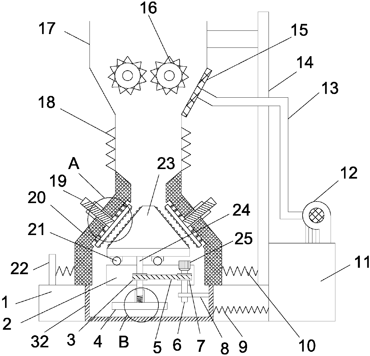
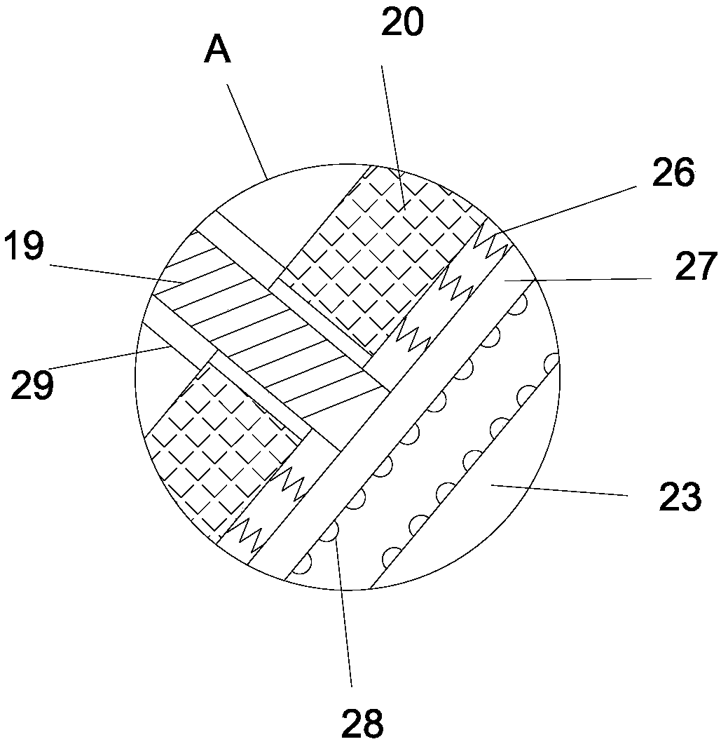
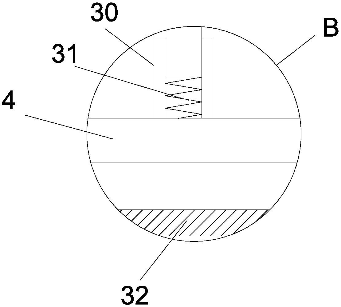
[0019] see Figure 1-3 , an eccentric rotary cone type stone crushing device for mineral processing, comprising a bottom box 1, the upper right end of the bottom box 1 is vertically welded and fixed with a column 14, the inside of the bottom box 1 is hollow, and the inside of the bottom box 1 slides horizontally The grinding basket 32 is provided in the type, and the first return spring 9 is connected between the grinding basket 32 and the inner wall on the right side of the bottom box 1. The horizontal sliding type on the bottom box 1 is provided with a conical cover plate 20, and the bottom box 1 is located on the cone. The left side of the shaped cover plate 20 is vertically fixed with a vertical plate 22, and the second return spring 10 is connected between the vertical plate 22 and the conical cover plate 20 and between the conical cover plate 20...
PUM
 Abstract
Description
Claims
Application Information