Grooving and perforating equipment for metal doors and windows

A technology for metal doors and windows and drilling equipment, applied in metal processing equipment, drilling/drilling equipment, metal processing machinery parts, etc., can solve the problems of large equipment size, incomplete functions, expensive prices, etc., to ensure quality and accuracy Effect

Inactive Publication Date: 2018-01-09
ZHEJIANG DEQING DETAI DOOR IND
View PDF0 Cites 6 Cited by
  • Summary
  • Abstract
  • Description
  • Claims
  • Application Information

AI Technical Summary

Problems solved by technology

[0002] Metal doors and windows are generally made of stainless steel. It is required that stainless steel for metal doors and windows must have strong anti-corrosion performance and unique stainless steel luster. The thermal insulation performance must be better than that of ordinary steel with the same structure. The requirements are also constantly increasing, and it needs to have sufficient transverse yield strength and corrosion resistance; and in some cold regions, the low-temperature toughness of stainless steel is not high, and it often leads to fracture in a short time
Therefore, how to effectively improve the transverse yield strength, corrosion resistance and low-temperature toughness of stainless steel for metal doors and windows is a technical problem that has been needed to be solved by those skilled in the art; 1. On-site workers have high labor intensity and low work efficiency. Several or dozens of on-site operators are required to work synchronously in front of different equipment, which is inconvenient in personnel deployment or management. In addition, when on-site operations, especially For operations such as punching, grooving, and truncation, there are still potential safety hazards
Although researchers have also proposed some automatic control equipment, however, this type of control equipment is expensive, has incomplete functions, and has a high failure rate.

Method used


Image

  • Grooving and perforating equipment for metal doors and windows
  • Grooving and perforating equipment for metal doors and windows
  • Grooving and perforating equipment for metal doors and windows

Examples


Embodiment Construction

[0026] The following will clearly and completely describe the technical solutions in the embodiments of the present invention with reference to the accompanying drawings in the embodiments of the present invention. Obviously, the described embodiments are only some, not all, embodiments of the present invention. Based on the embodiments of the present invention, all other embodiments obtained by persons of ordinary skill in the art without making creative efforts belong to the protection scope of the present invention.

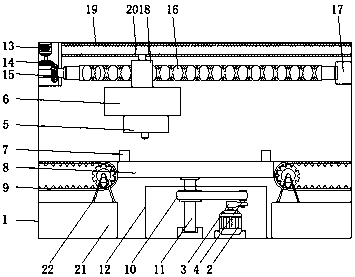
[0027] see Figure 1-4 , the present invention provides a technical solution: a metal door and window slotting and punching equipment, including a work box 1, a workbench power box 12 is fixedly connected to the middle position of the bottom of the inner wall of the work box 1, and the bottom of the inner wall of the workbench power box 12 is fixedly connected There is a power motor 2, the power motor 2 is connected with a deceleration connector 3 through the ...


PUM


Abstract

The invention discloses a slotting and punching device for metal doors and windows, which comprises a working box, a workbench power box is fixedly connected to the middle of the bottom of the inner wall of the workbox, and a power motor is fixedly connected to the bottom of the inner wall of the workbench power box. The power motor is rotatably connected to a deceleration connector through an output shaft, and the output shaft of the deceleration connector is fixedly connected to a first pulley through a flat key, and the first pulley is rotatably connected to a second pulley through a belt. The present invention relates to metal door and window processing technology field. The metal door and window slotting and punching equipment solves the transmission and positioning of the workpiece, the change of the position of the workbench and the positioning of the punching device, ensures the stable fixing of the workpiece and the working environment in different directions, and ensures the stable positioning of the punching device , to ensure the accuracy of the workpiece and the stability of the drilling device moving up and down and the power output of the drill bit, and to ensure the quality and accuracy of its punching or slotting.

Description

technical field [0001] The invention relates to the technical field of processing metal doors and windows, in particular to a slotting and punching equipment for metal doors and windows. Background technique [0002] Metal doors and windows are generally made of stainless steel. It is required that stainless steel for metal doors and windows must have strong anti-corrosion performance and unique stainless steel luster. The thermal insulation performance must be better than that of ordinary steel with the same structure. The requirements are also constantly increasing, and it needs to have sufficient transverse yield strength and corrosion resistance; and in some cold regions, the low-temperature toughness of stainless steel is not high, and it often leads to fracture in a short time. Therefore, how to effectively improve the transverse yield strength, corrosion resistance and low-temperature toughness of stainless steel for metal doors and windows is a technical problem that...

Claims


Application Information

Patent Timeline
Patent Type & Authority Applications(China)
IPC IPC(8): B23B47/26B23Q5/26B23Q5/38
Inventor 唐红娟
Owner ZHEJIANG DEQING DETAI DOOR IND
Why Eureka
Try Eureka