Alga control system based on water surface floating type photovoltaic power generation station

A photovoltaic power station, water surface floating technology, applied in water aeration, floating buildings, water/sludge/sewage treatment, etc., can solve the problems of high energy consumption in long-distance transportation, large investment in shading, and low wind and wave resistance. , to solve the problems of long-distance power supply and gas transmission, improve the efficiency of algae control, and have strong wind and wave resistance.

Pending Publication Date: 2018-01-09
南京瑞盛环保技术有限公司 +1
View PDF1 Cites 1 Cited by
  • Summary
  • Abstract
  • Description
  • Claims
  • Application Information

AI Technical Summary

Problems solved by technology

[0009] At present, existing shading algae control technology, such as Kojima Sadao's shading study on algal control by partial shading of lake surface [J]. Main-Water and Wastewater, 2000, 42 (5) :5-12) show that it is necessary to cover about 1/3 of the water surface to achieve the effect of algae control. When applied to large water surfaces (lakes and medium and large reservoirs), the shading area required for shading control of algae control is very large; Kong Hainan’s Algae control technology (Kong Hainan et al., Method for Controlling Water Bloom in Eutrophic Reservoir, CN 101456603 B) aeration and oxygenation air transport distance is short, long-distance transport energy consumption is high, and it is used for near-shore layo

Method used


Image

  • Alga control system based on water surface floating type photovoltaic power generation station
  • Alga control system based on water surface floating type photovoltaic power generation station
  • Alga control system based on water surface floating type photovoltaic power generation station

Examples


Embodiment Construction

[0031] The following introduces some of the possible embodiments of the present invention, which are intended to provide a basic understanding of the present invention, but are not intended to identify key or decisive elements of the present invention or limit the scope of protection. It is easy to understand that, according to the technical solution of the present invention, those skilled in the art may propose other alternative implementation manners without changing the essence and spirit of the present invention. Therefore, the following specific embodiments and drawings are only exemplary descriptions of the technical solution of the present invention, and should not be regarded as the entirety of the present invention or as a limitation or restriction on the technical solution of the present invention.

[0032] In the following description, for the sake of clarity and conciseness of description, not all components shown in the figures are described, and a plurality of com...


PUM


Abstract

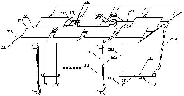
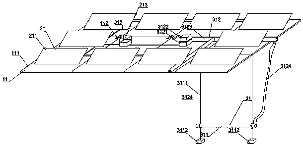
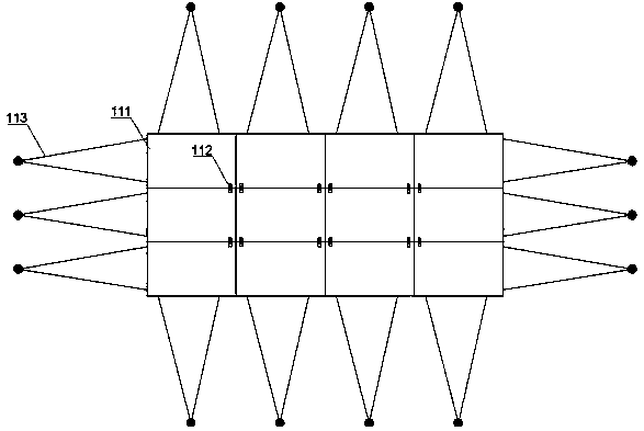
The invention discloses an alga control system based on a water surface floating type photovoltaic power generation station. The alga control system comprises a water surface floating device, and a photovoltaic power generation device and an oxygen inflation device which are arranged on the water surface floating device, wherein the floating device is formed by splicing floating single bodies; after the floating single bodies are spliced, complete shielding or incomplete shielding is formed on a water surface; the oxygen inflation device comprises a gas supply system located above the water surface and an aeration device located below the water surface; gas is supplied to the aeration device by the gas supply system; the photovoltaic power generation device is used for supplying power to the gas supply system. According to the alga control system disclosed by the invention, the photovoltaic power generation device, the aeration and oxygen inflation devices and a flow push device are integrally arranged by utilizing the water surface floating device and share the water surface floating device, so that algae are effectively controlled and photovoltaic power generation can be realizedto provide green electric energy; the alga control system has the advantages of cost reduction, good comprehensive benefits, greenness and environment protection.

Description

technical field [0001] The invention belongs to the field of environmental protection technology for treating polluted water and photovoltaic power generation technology, and relates to an integrated system of shading, oxygenation, algae control and photovoltaic power generation. Background technique [0002] At present, lakes and reservoirs in my country are generally eutrophic, algae blooms occur frequently, and eutrophication of water bodies has brought serious water environment problems. In my country's algal blooms, cyanobacteria are often the dominant algae species. Cyanobacteria secrete and release harmful gases and toxins, which endanger human health through the accumulation of food chains, threaten the safety of urban water supply and affect aquaculture, tourism and human life. Therefore, it is of great significance to control and remove harmful algae in water bodies. [0003] The main factors causing algal blooms: nutrients (nitrogen, phosphorus, etc.), temperatur...

Claims


Application Information

Patent Timeline
IPC IPC(8): C02F7/00B63B35/44
CPCY02W10/10
Inventor 陆利锋王志强曹建锋白强沈杰郁伟杰顾华敏邓霞曹素兰
Owner 南京瑞盛环保技术有限公司
Why Eureka
Try Eureka