Punitive speed bump based on dampers and rubber air spring

A technology of rubber air springs and dampers, which is applied to roads, road signs, traffic signals, etc., can solve problems such as severe bumps, and achieve the effect of reducing height

Active Publication Date: 2018-01-09
GUIZHOU UNIV
View PDF8 Cites 4 Cited by
  • Summary
  • Abstract
  • Description
  • Claims
  • Application Information

AI Technical Summary

Problems solved by technology

The speed reduction belt can play a very good role in forcing the speed limit of the driving vehicle, but because the existing speed reduction belt mainly uses the principle of discomfort caused by the bumps when the vehicle is driving, so that the driver drives at the speed limit. The following conditions will still be plagued by this discomfort, so it is necessary to invent a speed bump that is stable at low speeds (or without bumps) when the vehicle is running at high speeds.

Method used


Image

  • Punitive speed bump based on dampers and rubber air spring
  • Punitive speed bump based on dampers and rubber air spring

Examples


Embodiment Construction

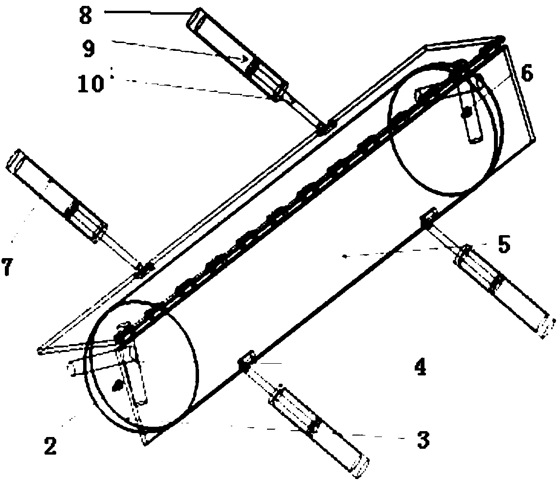
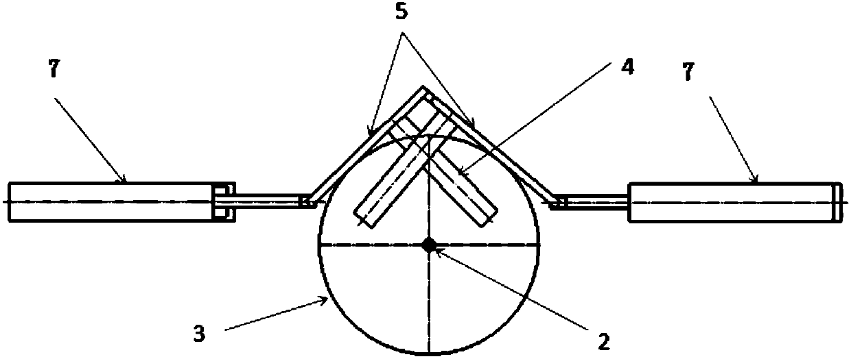
[0015] Embodiment of the present invention: a punishing speed bump based on a damper and a rubber air spring, as shown in the accompanying drawings, includes two speed bumps 5, and the two speed bumps 5 are hinged to form an inverted "cross section" V" structure, rubber air spring 3 is set in the V-shaped space of two speed brakes 5, an air inlet check valve 2 is set at one end of the rubber air spring 3, and an air outlet check valve 6 is set at the other end.

[0016] Wherein the caliber of the air inlet check valve 2 is smaller than the caliber of the air outlet check valve 6, the damper group 7 is arranged symmetrically at the bottom of the two speed brakes 5 and the damper group 7 is hinged to the bottom of the speed brake 5 connected, the damper 7 is fixed on the ground and kept flat with the ground, the damper includes a bar body 8, the piston 9 is placed in the bar body 8, a piston rod 10 is arranged on the side of the piston 9 and the piston rod 10 is hinged on the dec...


PUM


Abstract

The invention discloses a punitive speed bump based on dampers and a rubber air spring. The punitive speed bump comprises two speed decrease plates that form a structure with inverted-V-shaped cross section via hinging connection, the rubber air spring is arranged in a V-shaped space of the two speed decrease plates, one end of the rubber air spring is provided with an intake port one-way valve, and the other end of the rubber air spring is provided with an exhaust port one-way valve. The troubles caused by rigid speed bumps to vehicle drivers passing by stably are solved; frequency bumping may also affect lives and comfort of vehicles; the height of the punitive speed bump is adjusted according to vehicle speed when a vehicle passes by the punitive speed bump; the punitive speed bump is simple in structure, convenient to manufacture and high in practicality.

Description

technical field [0001] The invention relates to the technical field of municipal highway facilities, in particular to a punitive speed bump based on a damper and a rubber air spring. Background technique [0002] The speed bump is installed on the highway, the entrance of the community, the entrance and exit of the underground parking garage, and the downhill road section that needs to be decelerated to slow down the passing vehicles. The shape is generally strip-shaped or dot-shaped, and the material is mainly rubber. ; Generally, yellow and black are used to attract visual attention, and the road surface is slightly arched to achieve the purpose of vehicle deceleration. The deceleration belt achieves deceleration by affecting the driver's driving psychology; when the vehicle passes through the deceleration belt at a higher speed, severe vibration It will be transmitted from the tire to the driver through the body and seat. The vertical curve can generate a vertical acceler...

Claims


Application Information

Patent Timeline
Patent Type & Authority Applications(China)
IPC IPC(8): E01F9/529
Inventor 周滔赵津袁征席阿行
Owner GUIZHOU UNIV
Why Eureka
Try Eureka