
Composite underground anti-seepage isolation wall structure and construction method

A construction method and separation wall technology, applied to underwater structures, infrastructure engineering, artificial islands, etc., can solve problems such as shortened service life, easy breakdown of barriers, and limited application range, so as to reduce leaching and prevent physical damage , to ensure the effect of service life

Inactive Publication Date: 2018-01-09
SUZHOU UNIV +1
View PDF5 Cites 3 Cited by
  • Summary
  • Abstract
  • Description
  • Claims
  • Application Information

AI Technical Summary

Problems solved by technology

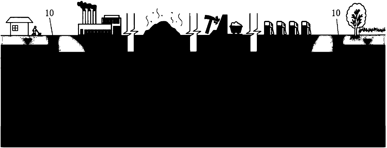
Although the compatibility of bentonite to pollutants is better than that of cement, the strength of the cut-off wall formed is low, and the scope of application is limited, and the seepage barrier performance of the wall is generally difficult to meet the specification requirements under the erosion of high-concentration composite pollutants anti-seepage standard
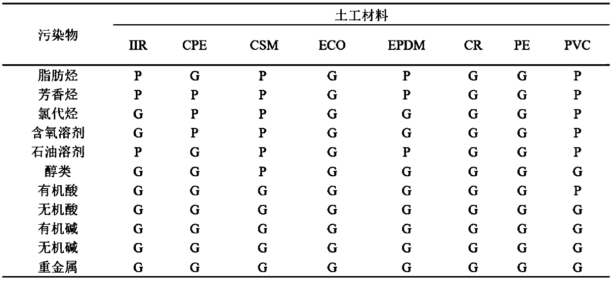
[0005] Although the geomembrane-bentonite composite separation wall has a low permeability coefficient and good isolation effect, the pollution site in the project is often dominated by compound pollution, often with the coexistence of various heavy metals and organic pollutants, and the pollution situation is extremely complicated. image 3 As shown in the table, the conventional single type of geotechnical material has certain limitations, and in the case of complex pollution, the leachate and the large amount of pollutants it carries are more likely to break through the barrier, greatly shortening the service life, so this single structure It is difficult for the separation wall to meet the complex pollution and seepage prevention requirements

Method used


Image

  • Composite underground anti-seepage isolation wall structure and construction method
  • Composite underground anti-seepage isolation wall structure and construction method
  • Composite underground anti-seepage isolation wall structure and construction method

Examples


Embodiment Construction

[0041] The specific implementation manners of the present invention will be further described in detail below in conjunction with the accompanying drawings and embodiments. The following examples are used to illustrate the present invention, but are not intended to limit the scope of the present invention.

[0042] Refer to attached Figure 4 , a composite underground anti-seepage partition wall structure in this embodiment, it comprises a vertically arranged wall body 1, at least two layers of functional layers 2 arranged in the wall body 1, and the setting direction of the functional layer 2 is the same as that of the wall body 1 parallel, at least one functional layer 2 is plate-shaped. The materials used for each functional layer 2 are different. attached Figure 4 The middle arrow indicates the direction of pollutant penetration.

[0043] In a more preferred embodiment, all the functional layers 2 can be made of plate-shaped materials, or both film-shaped materials a...


PUM


Abstract

The invention discloses a composite underground anti-seepage isolation wall structure and a construction method. The composite underground anti-seepage isolation wall structure comprises a vertically-arranged wall and at least two functional layers arranged in the wall and made of different materials. The arranging direction of the functional layers is parallel to the wall, and at least one functional layer is in a plate shape. The construction method based on the above composite underground anti-seepage isolation wall structure comprises the following steps that a, the position where the anti-seepage isolation wall needs to be arranged is excavated to form a groove, wall materials are injected into the groove, and a functional layer platy material is inserted in the wall materials; b, theplaty material is inserted to the design elevation; c, a second platy material is inserted side by side, the two platy materials are connected through a buckle so that the joint sealing quality can be ensured, and percolate leaching is prevented; d, the second play material is inserted to the design elevation; and e, according to the step c and the step d, subsequent platy materials are continuously and circularly inserted till construction is finished.

Description

technical field [0001] The invention relates to a composite underground anti-seepage separation wall structure and a construction method. Background technique [0002] In recent years, my country's urbanization process is very rapid, and the level of industrial and municipal environmental protection infrastructure construction and operation management is relatively lagging behind, resulting in increasingly serious urban groundwater and soil pollution in my country. Soil pollution is defined as: Harmful and toxic substances produced by human activities enter the soil and accumulate to a certain extent, exceeding the self-purification capacity of the soil itself, resulting in changes in soil properties and quality, which constitute impacts and hazards on the human body and the ecological environment. Due to the effects of rain and scouring, leachate containing harmful components will inevitably be produced. If no effective anti-seepage measures are taken, the leachate will mig...

Claims


Application Information

Patent Timeline
Patent Type & Authority Applications(China)
IPC IPC(8): E02D29/045E02D29/16E02D31/00E02D31/06
Inventor 唐强徐宇良温惠清陆聪张余邓志鑫蒋润杰陈鑫
Owner SUZHOU UNIV
Learn More