Spiral type heating dryer with materials being loaded separately

A screw type, dryer technology, applied in dryers, non-progressive dryers, drying and other directions, can solve the problems of prolonging the residence time of the dryer, reducing the drying efficiency of the device, and low drying efficiency, and achieves wetting. The effect of large angle, high temperature hardness and low bubble rate

Inactive Publication Date: 2018-01-09
兰溪市捷喜食品加工技术有限公司
View PDF7 Cites 1 Cited by
  • Summary
  • Abstract
  • Description
  • Claims
  • Application Information

AI Technical Summary

Problems solved by technology

[0003] The prior art, such as the Chinese invention authorized patent document, the authorized announcement number CN 104315825 B, this invention discloses a kind of airflow drying equipment with double helix structure, the equipment of this invention uses hot air duct to send hot air flow and humid air to the outer drying cylinder. The material, under the action of the hot air flow, the material moves downward spirally along the top surface of the guide plate, and is dried in the outer drying cylinder. The spiral upward airflow in the cylinder drags the material spirally upward and discharges from the top opening of the inner drying cylinder, which reduces the height of the equipment and prolongs the residence time of the material in the dryer. It has good drying performance, operation, small size and low cost. The advantages of low cost, but the spiral structure of the device will cause the wet material to accumulate at the junction of the guide plate and the inner wall of the outer drying cylinder and the junction of the guide plate and the outer wall of the inner drying cylinder, thereby reducing the drying efficiency of the device and even causing damage to the device , and because the size of the inner drying cylinder is too narrow, the induced draft fan at the top is not enough to absorb the material from the bottom of the cylinder to the top outlet, which will cause low drying efficiency and waste of energy

Method used


Image

  • Spiral type heating dryer with materials being loaded separately

Examples


Embodiment 1

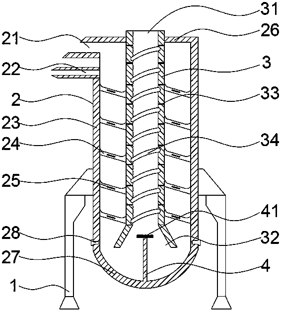
[0019] Such as figure 1 As shown, the spiral heating dryer for object packaging includes a support column 1, an outer drying cylinder 2 supported by the support column 1 and fixedly connected, and an outer drying cylinder 2 nested inside the outer drying cylinder 2 and arranged coaxially with the outer drying cylinder 2. The inner drying cylinder 3 has four support columns and is symmetrically distributed around the outer drying cylinder 2. The outer drying cylinder 2 includes an outer cylinder body 23 with upper and lower ends open, which is fixedly connected to the upper end of the outer cylinder body 23 and sealed. 23, the top cover 26 with the upper end open, the cylinder bottom 27 that is fixedly connected to the lower end of the outer cylinder 23 and seals the lower end opening of the outer cylinder 23, and the top end of the upper part of the side wall of the outer cylinder 23 is provided with a feed port 21 that runs through the side wall of the outer cylinder , the ho...

Embodiment 2

[0027] Such as figure 1 As shown, the spiral heating dryer for separate packaging of objects, after the power is turned on, the outer drying cylinder 2 is fixedly connected with support columns 1 for supporting this embodiment. The part is connected with the heater, and is used to transmit the hot air flow to the outer drying cylinder 2. Since the outer cylinder body 23 is provided with a spiral downward guide plate 24, when the wet material is added from the feed port 21, the wet material is in the hot air flow. Under the action, it moves downward in a spiral along the upper end surface of the guide plate 24, and is dried in the outer drying cylinder 2; There is a spiral upward airflow in the drying cylinder 3. When the material moves downward to the bottom 27 of the cylinder, the dried material is entrained by the airflow and is driven by the suction fan 41 and the air flow of the induced draft fan to move upward from the inner drying cylinder 3. After further drying, it is...


PUM


Abstract

The invention provides a spiral type heating dryer with materials being loaded separately, and belongs to the field of industrial dryers. The spiral type heating dryer comprises an outer drying cylinder, an inner drying cylinder and a supporting column, wherein the supporting column supports and is fixedly connected with the outer drying cylinder; the outer drying cylinder comprises an outer cylinder body, a top cover and a cylinder bottom, wherein openings are formed in the upper end and the lower end of the outer cylinder body, the top cover is fixedly connected with the upper end of the outer cylinder body and seals the opening at the upper end of the outer cylinder body, and the cylinder bottom is fixedly connected with the lower end of the outer cylinder body and seals the opening atthe lower end of the outer cylinder body; a strut is mounted in the center of the cylinder bottom, a suction fan is mounted at the top end of the strut, and the top end of the upper part of the side wall of the outer cylinder body is provided with a material inlet and a hot air pipeline which penetrate through the side wall of the outer cylinder body; the inner drying cylinder and the outer cylinder body are arranged coaxially; a guiding plate with a downward spiral is arranged on the area between the inner wall of the outer cylinder body and the outer wall of the inner drying cylinder, and agroove with an upward spiral is formed in the inner wall of the inner wall of the inner drying cylinder; and a first heating element is arranged in the cylinder wall of the inner drying cylinder, anda second heating element is arranged in the guiding plate. According to the double spiral structure of the spiral type heating dryer, damp materials can be quickly and evenly dried, and adhesion and hardening of the materials in the dryer is not easy to occur.

Description

technical field [0001] The invention relates to the field of industrial dryers, in particular to a spiral heating dryer for separate packing of objects. Background technique [0002] Dryers can be divided into industrial and civilian. Industrial dryers are also called drying equipment or dryers. Civilian dryers are one of washing machines. They are generally used to remove clothing and other textiles after washing and dehydration. of moisture. The dryer has several modes such as belt drying, drum drying, box drying, and tower drying; the heat source includes coal, electricity, gas, etc.; the drying process of materials has hot air flow type and radiation type, etc. , hot air drum drying is that the hot air flow moves forward from the tail, fully contacts with the material, and makes full use of the heat transfer through heat conduction, convection, and radiation; the heat energy is directly transferred to the material, so that the moisture of the material is continuously ev...

Claims


Application Information

Patent Timeline
Patent Type & Authority Applications(China)
IPC IPC(8): F26B11/00F26B21/00F26B25/08
Inventor 张庆吉
Owner 兰溪市捷喜食品加工技术有限公司
Why Eureka
Try Eureka