

Stator winding of AC generator
A technology of alternator and stator winding, which is applied to the shape/pattern/structure of winding conductors, the shape/pattern/structure of magnetic circuit, the static parts of magnetic circuit, etc. It is difficult to use manual or mechanical offline, 48V system cannot generate high-speed power, etc., to achieve the effect of regular connection and outlet, uniform size of winding and coil, and reduced end size
- Summary
- Abstract
- Description
- Claims
- Application Information
AI Technical Summary
Problems solved by technology
Method used
Image

Examples
Embodiment 1
[0027] Example 1: 6-pitch stator winding with 3-phase 2-way parallel connection
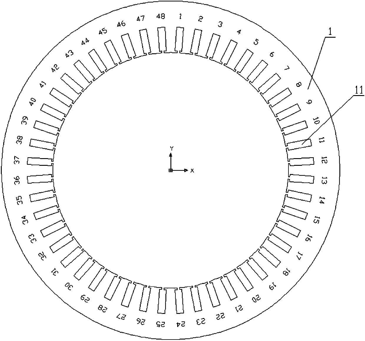
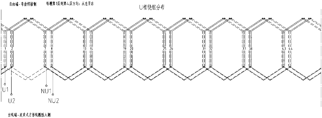
[0028] In the 6-pitch stator winding (U1, U2 / V1, V2 / W1, W2) that implements three-phase 2-way parallel connection, if the outlet terminals of the first phase U-phase are set to two arbitrary adjacent slots, Such as image 3 with Figure 4 As shown, in this embodiment, the first slot and the second slot are selected as the outlet terminals U1 and U2 of the U phase respectively, then the coils to be connected to U1 are distributed in slot 1, slot 7, slot 13, slot 19, slot 25, and slot 31 In slot 1, slot 37 and slot 43, the coils to be connected to U2 are distributed in slot 2, slot 8, slot 14, slot 20, slot 26, slot 32, slot 38 and slot 44.
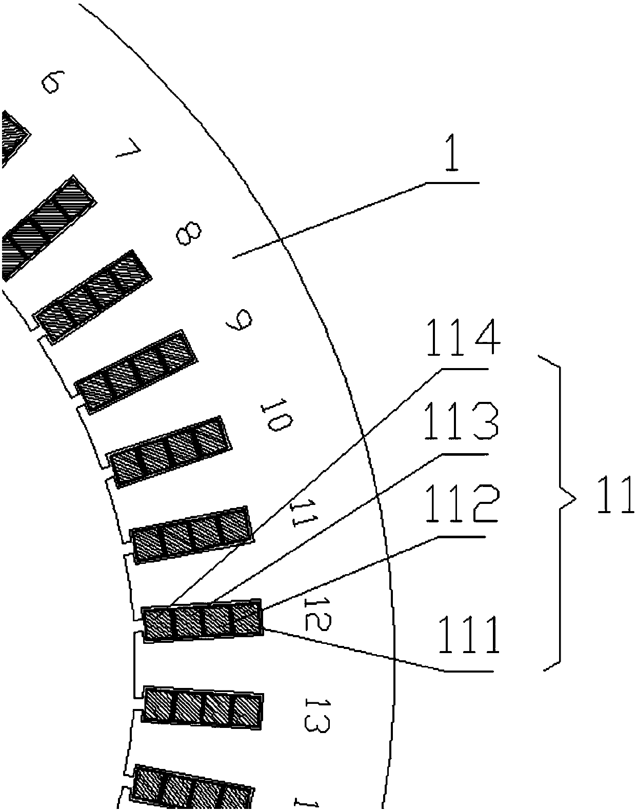
[0029] In this embodiment, the specific connection method of U1 is as follows: place the lead wires in the second layer of the first slot; insert a large hairpin square coil into the first layer of the seventh slot and the 4th layer of the 13th slot, wher...
Embodiment 2
[0033] Example 2: 6-pitch stator winding with three-phase and one parallel connection
[0034] In the 6-pitch stator winding (U1, U2 / V1, V2 / W1, W2) that implements three-phase 1-way parallel connection, if the U-phase outlet is set to two arbitrary adjacent slots, such as image 3 with Figure 4 As shown, in this embodiment, the first slot and the second slot are selected as the outlet terminals U1 and U2 of the U phase respectively, and the coils to be connected to U1 are distributed in slot 1, slot 7, slot 13, slot 19, slot 25, and slot 31 , 37 and 43 slots, the coils to be connected to U2 are distributed in 2 slots, 8 slots, 14 slots, 20 slots, 26 slots, 32 slots, 38 slots and 44 slots.
[0035] In this embodiment, the specific connection method of U1 is as follows: place the lead wires in the second layer of the first slot; insert a large hairpin square coil into the first layer of the seventh slot And the 4th layer of the 13th slot, where the legs placed on the 1st la...
PUM
| Property | Measurement | Unit |
|---|---|---|
| Opening width | aaaaa | aaaaa |
Abstract
Description
Claims
Application Information