A hydraulic type biogas digester with automatic feeding and discharging and its automatic feeding and discharging method
A technology for feeding and discharging materials and biogas digesters, which is applied in the direction of waste fuel and gas production bioreactors, etc. It can solve the problems of affecting crop sowing, incomplete fermentation, and easy floating of straw, so as to improve the utilization rate of tank capacity and fermentation efficiency, reduce The effect of large discharge frequency and reduction of fermentation blind spots
- Summary
- Abstract
- Description
- Claims
- Application Information
AI Technical Summary
Problems solved by technology
Method used
Image
Examples
Embodiment 1
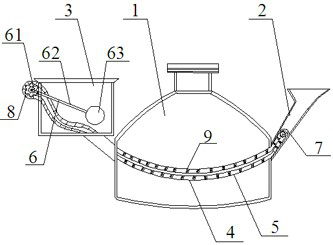
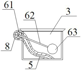
[0029] A hydraulic biogas digester with automatic feeding and discharging, such as figure 1 As shown, it includes a fermentation tank 1 and a feed pipe 2 and a hydraulic room 3 communicating with the body of the fermentation tank 1, and also includes an automatic feeding and discharging device 4 that traverses the feed pipe 2, the fermentation tank 1 and the hydraulic room 3, This automatic feeding and discharging device 4 can be disassembled and separated according to the situation or installed in the biogas digester; the automatic feeding and discharging device 4 includes a pipe chain conveyor belt 5 and a driving device 6; the pipe chain conveyor belt 5 (such as Figure 5 shown) includes a delivery pipe 51 and a transmission chain 52 worn in the delivery pipe; the transmission chain 52 is composed of a plurality of end-to-end chains 521, and a plurality of transmission plates 522 are equidistantly arranged on the transmission chain 52, so The transmission plate 522 fits the...
Embodiment 2
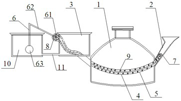
[0035] The biogas digester described in embodiment 2 (such as figure 2 shown) is substantially the same as that described in Embodiment 1, the difference is that a communicating room 10 is set, and the communicating room 10 communicates with the hydraulic room 3 through the communicating device 10, and the bottom surface of the communicating room 10 and the bottom surface of the hydraulic room 3 The heights are the same, one end of the connecting device 11 is set at the bottom of the communicating room 10 , and the other end is set at the bottom of the water pressure room 3 . The floating ball 63 is located in the communication room 10, and the lever 62 is in a bent shape, connecting the floating ball 63 and the one-way gear 61 fixed on the outer wall of the hydraulic room 3. Other structures and methods of use are the same as in Example 1.
[0036] Both embodiment 1 and embodiment 2 rely on the power generated by the lifting of the floating ball to drive the transmission ch...
PUM
| Property | Measurement | Unit |
|---|---|---|
| radius | aaaaa | aaaaa |
Abstract
Description
Claims
Application Information
 - R&D
- Intellectual Property
- Life Sciences
- Materials
- Tech Scout
- Unparalleled Data Quality
- Higher Quality Content
- 60% Fewer Hallucinations
Browse by: Latest US Patents, China's latest patents, Technical Efficacy Thesaurus, Application Domain, Technology Topic, Popular Technical Reports.
© 2025 PatSnap. All rights reserved.Legal|Privacy policy|Modern Slavery Act Transparency Statement|Sitemap|About US| Contact US: help@patsnap.com


