Torque sensor device based on fiber gratings

A technology of torque sensor and optical fiber grating, which is applied in the direction of measuring devices, instruments, torque measurement, etc., can solve problems affecting the stability and accuracy of measurement, measurement signal fluctuations, instability, etc., and achieve simple and easy measurement, overall High sensitivity and the effect of avoiding chirp phenomenon

Inactive Publication Date: 2018-01-12
WUHAN UNIV OF TECH
View PDF6 Cites 2 Cited by
  • Summary
  • Abstract
  • Description
  • Claims
  • Application Information

AI Technical Summary

Problems solved by technology

[0003] For the traditional strain gauge measurement method, the strain gauge is pasted on the surface of the shaft. When the shaft is twisted and deformed, the strain transmitted to the strain gauge is not equal, which will make the measurement signal fluctuate and unstable. In practice, due to the elimination of The lateral force such as the gravity of the parts on the shaft causes the bending strain generated by the shaft, and a plurality of strain gauges are symmetrically pasted on the shaft to realize the difference, which will undoubtedly further increase the instability of the signal. The photoelectric measurement method requires relatively high precision of photoelectric components. , while the magnetoelectric and magnetoelastic measurement methods are susceptible to electromagnetic interference, which affects the stability and accuracy of the measurement. The magnetoelastic measurement method can only be applied to the rotating shaft of ferromagnetic materials.

Method used


Image

  • Torque sensor device based on fiber gratings
  • Torque sensor device based on fiber gratings
  • Torque sensor device based on fiber gratings

Examples


Embodiment Construction

[0017] The present invention will be further described below in conjunction with the embodiments and the accompanying drawings.

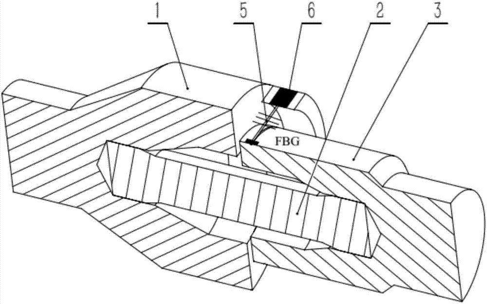
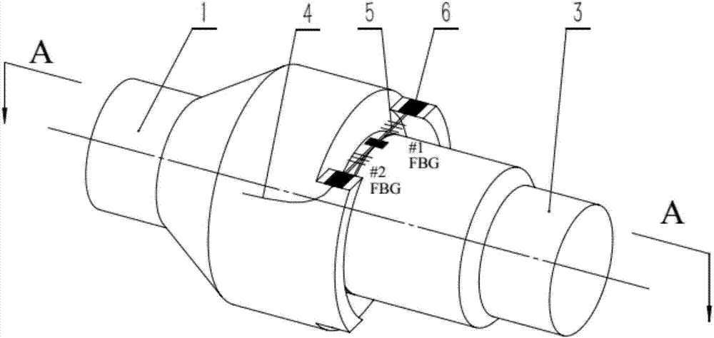
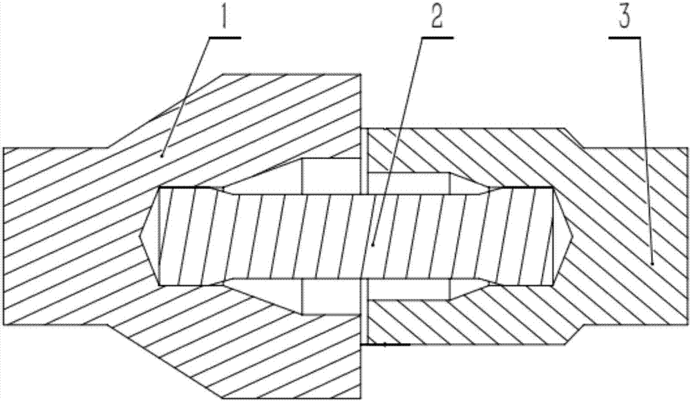
[0018] Such as Figure 1 to Figure 3 As shown, a torque sensor device based on a fiber grating 5 includes a fiber grating 5 and a coaxial input shaft 1, torsion bar 2 and output shaft 3, and the two ends of the torsion bar 2 are respectively connected to the input shaft 1 and the The output shaft 3 is connected. One end of the input shaft 1 is provided with a partial ring-shaped protrusion that is symmetrical about the axis. The outer surface of the output shaft 3 is provided with a groove. The optical fiber is tensioned in a straight line and is tangent to the output shaft 3. It is fixed on part of the ring-shaped protrusion by glue 6, and fixed on the groove by glue 6 in the middle. There are two suspended gratings evenly distributed between the three fiber fixing points. The pigtail 4 is close to and along the input axis 1. Lead out from the sur...


PUM


Abstract

The invention relates to a torque sensor device based on fiber gratings. The device comprises the fiber gratings, an input shaft having the same axis as the fiber grating, a torsion rod and an outputshaft, wherein two ends of the torsion rod are connected with the input shaft and the output shaft through a spline, one end of the input shaft is provided with partially-annular projections symmetricto the axis, an outer circumferential surface of one end of the output shaft is provided with a groove, fiber is tensioned in a straight line mode and is tangent to the output shaft, two ends of thefiber are fixed with the partially-annular projections, the middle of the fiber is fixed on the groove, two suspended gratings are uniformly distributed among three fiber fixing points, and a tail fiber fits the surface of the input shaft, is led out along the surface of the input shaft and is then connected with a rotary connector. The device is advantaged in that a relative torsion angle is converted into stretching or compression deflection of the fiber, torque can be acquired through measuring wavelength drift amount of the fiber grating, measurement is simple and easy, anti-electromagnetic interference and temperature compensation functions are realized, sensitivity is high, and signal stability is further realized.

Description

technical field [0001] The invention belongs to the field of torque measurement, and in particular relates to a torque sensor device based on an optical fiber grating. Background technique [0002] At present, there are mainly several methods for measuring the torque of the rotating shaft, such as strain gauge, photoelectric, magnetoelectric, and magnetoelastic. The strain gauge type sensor is to directly paste the strain bridge on the shaft to measure the torsional deformation of the shaft to obtain the torque, and obtain the torque signal through wired or wireless transmission; the photoelectric sensor installs the photoelectric element on the shaft. When the shaft is stressed, The light intensity received by the photoelectric element changes, and the photoelectric element (such as a combination of grating and photoelectric triode) converts the change of light intensity obtained from the light source into the change of the output pulse current to achieve the purpose of tor...

Claims


Application Information

Patent Timeline
Patent Type & Authority Applications(China)
IPC IPC(8): G01L3/08
Inventor 魏莉王兢兢余玲玲
Owner WUHAN UNIV OF TECH
Why Eureka
Try Eureka