Battery electrolyte ultrasonic injection equipment and method

A technology of injecting equipment and ultrasonic waves, applied in battery pack parts, circuits, electrical components, etc., can solve the problems of plate performance fluctuation, failure, space for multiple battery parts, etc., to improve absorption and infiltration, accelerate absorption and infiltration, The effect of more absorption space

Pending Publication Date: 2018-01-12
ZHONGYIN NINGBO BATTERY CO LTD
View PDF4 Cites 3 Cited by
  • Summary
  • Abstract
  • Description
  • Claims
  • Application Information

AI Technical Summary

Problems solved by technology

[0006] With the pursuit of battery capacity in power lithium battery technology, the plates and separators in the battery are increasingly pursuing the ultimate high density, which not only takes up more space in the battery, but also causes the electrolyte to be trapped in and between the plates. The penetration between the plates is more difficult, so despite the use of vacuum filling and vacuum multiple filling technologies, due to the high density of the battery plate, the penetration of the electrolyte between the plate and the plate is difficult, so the electrolyte filling the problem has always existed
[0007] At the same time, due to the performance fluctuation of the plate, and some problems such as liquid absorption and permeability of the plate, it is difficult to fully achieve satisfactory results by directly adding electrolyte at one time.
[0008] One of the quality problems of the battery is that due to incomplete penetration of the electrolyte in the electrodes, some electrodes fail without electrolyte
This is because as the battery capacity increases, the density and compactness of the electrodes become higher and higher. Due to the limited injection time of the electrolyte, it is impossible to ensure that the electrolyte has sufficient diffusion and penetration time in the battery, resulting in electrolysis. Liquid injection and penetration, poor infiltration

Method used


Image

  • Battery electrolyte ultrasonic injection equipment and method
  • Battery electrolyte ultrasonic injection equipment and method
  • Battery electrolyte ultrasonic injection equipment and method

Examples


Embodiment Construction

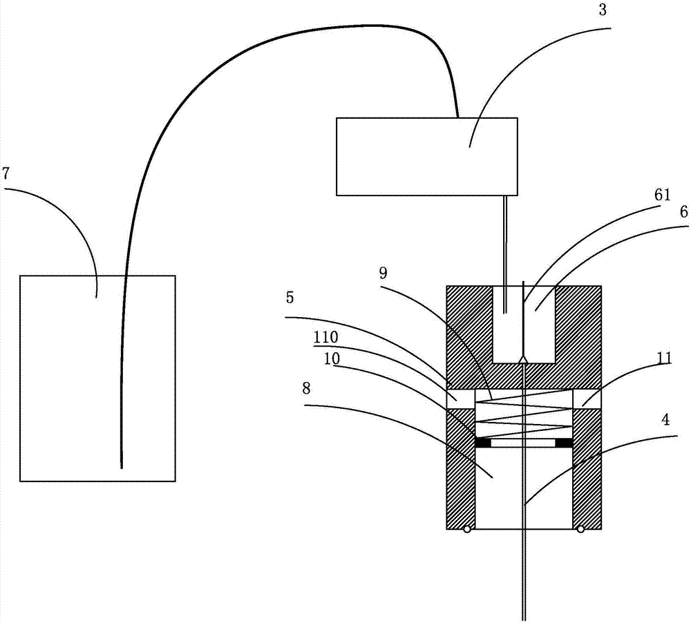
[0057] The present invention will be further described in detail below in conjunction with the accompanying drawings and embodiments.

[0058] Ultrasonic liquid injection can solve two problems in the traditional battery liquid injection process.

[0059] The first problem is the diffusion of the electrolyte between the plates: on the one hand, the ultrasonic waves vibrate the plates, forming gaps in an instant, and then closing them instantly. The gaps are generated and closed in an instant to form a pump valve effect, which greatly accelerates Diffusion of electrolyte between electrodes and inside electrodes.

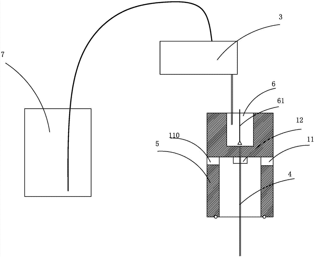
[0060] Another problem is the penetration and infiltration of the electrolyte in the plate: the process of the electrolyte being absorbed by the plate is the process of penetrating into the micropore gap of the plate and wetting the surface of the plate, and these micropores of the plate On the one hand, due to the existence of air in the gap, especially the air in t...


PUM


Abstract

The invention discloses battery electrolyte ultrasonic injection equipment and a battery electrolyte ultrasonic injection method. The battery electrolyte ultrasonic injection equipment comprises a base for placing one or more to-be-injected batteries, liquid injection devices which correspond to the corresponding to-be-injected batteries, and an ultrasonic generation device; each liquid injectiondevice comprises a metering pump and a liquid injection needle; and the ultrasonic generation device conducts ultrasonic wave into an electrolyte and an electrode coil in each battery. The battery electrolyte ultrasonic injection equipment and the battery electrolyte ultrasonic injection method have the following advantages: in the electrolyte injection process of the battery and after the batteryis vacuumized and part of or all the electrolyte is injected, ultrasonic wave is applied to the battery, so on one hand, the vacuumizing effect is improved, and on the other hand, the absorbing speedof the electrolyte between the electrodes and in the electrodes is increased; moreover, the injection quantity of the electrolyte is increased, and absorption and wetting on the electrolyte by the electrodes are improved, so that the performance of the battery is improved and the performance uniformity of the battery is improved.

Description

technical field [0001] The invention relates to a battery electrolyte injection device and method, in particular to a battery electrolyte ultrasonically enhanced absorption injection device and method. Background technique [0002] It is often said that the electrolyte is the blood of the battery. In fact, the electrolyte is not just the blood of the battery, because the electrolyte not only plays the role of transporting ions and conducting internal ions in the battery reaction, but in most cases the electrolyte It also participates in the electrode reaction of the battery, that is to say, during the charging and discharging process of the battery, especially during the discharging process, the electrolyte or the components in the electrolyte are actually consumed like the active materials, so the electrolyte in the battery is injected The amount, especially whether there is enough electrolyte in the battery directly affects the battery capacity and discharge performance, e...

Claims


Application Information

Patent Timeline
Patent Type & Authority Applications(China)
IPC IPC(8): H01M2/36H01M50/60
CPCY02E60/10
Inventor 谢红卫
Owner ZHONGYIN NINGBO BATTERY CO LTD
Why Eureka
Try Eureka