Check patentability & draft patents in minutes with Patsnap Eureka AI!

Precision grating displacement measurement system for scanning interference field exposure system and precision grating displacement measurement method

A grating displacement and exposure system technology, applied in the field of precision grating displacement measurement systems, can solve problems such as the decrease in measurement accuracy, and achieve the effects of improving quality and reducing environmental control costs

Active Publication Date: 2018-01-16
CHANGCHUN INST OF OPTICS FINE MECHANICS & PHYSICS CHINESE ACAD OF SCI
View PDF7 Cites 1 Cited by
  • Summary
  • Abstract
  • Description
  • Claims
  • Application Information

AI Technical Summary

Problems solved by technology

However, the measuring range of the diffraction grating displacement measurement system is restricted by the length of the measurement grating. For the scanning interference field exposure system for making meter-scale gratings, the existing diffraction grating displacement measurement system cannot be directly applied to the step direction displacement of the scanning interference field exposure system. measuring
[0005] Therefore, how to provide a measurement method that solves the problem that the laser interferometer is more sensitive to environmental influences due to the increase of the measurement stroke, reduces the cost of environmental control, and improves the quality of the grating diffraction wavefront is an urgent problem to be solved by those skilled in the art. technical problem

Method used


Image

  • Precision grating displacement measurement system for scanning interference field exposure system and precision grating displacement measurement method
  • Precision grating displacement measurement system for scanning interference field exposure system and precision grating displacement measurement method
  • Precision grating displacement measurement system for scanning interference field exposure system and precision grating displacement measurement method

Examples


Embodiment Construction

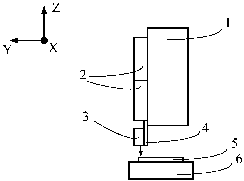
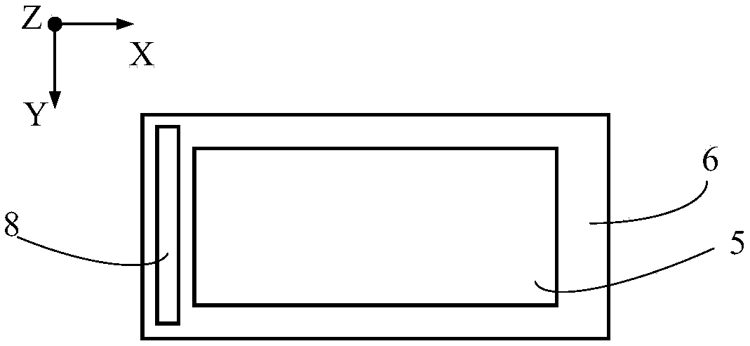
[0027] Embodiments of the present invention will now be described with reference to the drawings, in which like reference numerals represent like elements. In the accompanying drawings of the description of the present invention, in order to distinguish directions conveniently, the description attached Figure 1-9 The three-dimensional coordinates are marked. As mentioned above, such as figure 1 , figure 2 with image 3 As shown, the scanning interference field exposure system mainly includes: fixed platform 1, optical system 2, front-end optical system 3, front-end optical system fixed plate 4, grating substrate to be exposed 5, workbench 6, dual-frequency laser interferometer 7, measuring mirror 8. The dual-frequency laser interferometer 7 cooperates with the measuring mirror 8 to measure and position the table 6 along the stepping direction (X direction) on the one hand, and to measure the deflection of the table 6 when it moves along the scanning direction (Y directio...


PUM


Abstract

The invention discloses a precision grating displacement measurement system for a scanning interference field exposure system, which is characterized in that a long-travel high-precision diffraction grating displacement measurement system is introduced to both the front and the back of the scanning interference field exposure system, each grating displacement measurement system comprises a dual-frequency laser, a diaphragm and a reading head, the dual-frequency lasers, the diaphragms and the reading heads are respectively fixed at the same positions at the front and back of a laser fixing plate, the laser fixing plate is fixed at the bottom end of a marble platform, the diaphragm automatically controls whether emergent light of the dual-frequency laser gets into the reading head or not through a control system, and the reading head is integrated with an optical component and a receiver. The measurement system and method disclosed by the invention solve a problem that the measurement accuracy is reduced because a laser interferometer is more sensitive to environmental influences when the measurement range is increased, the environment control cost is reduced, and the grating diffraction wave front quality is improved.

Description

technical field [0001] The invention relates to the field of manufacturing large-scale gratings, in particular to a precision grating displacement measurement system and method for scanning interference field exposure systems. Background technique [0002] Scanning interference field exposure technology is one of the main ways to fabricate large-size, high-diffraction wavefront quality gratings. It not only has the advantages of easy realization of grating diffraction wavefront control by mechanical scribing technology, but also has the advantages of low stray light, no ghost lines and high production efficiency of holographic exposure technology. It uses interference fringes as "knife" and uses the same technology as mechanical scribing technology. Consistent scan-step exposure method for large-area grating production. Due to the small size of the interference field involved in the exposure, it is easier to control the diffraction wavefront of the grating. At the same time...

Claims


Application Information

Patent Timeline
IPC IPC(8): G01B11/02
Inventor 宋莹吕强李文昊刘兆武王玮巴音贺希格
Owner CHANGCHUN INST OF OPTICS FINE MECHANICS & PHYSICS CHINESE ACAD OF SCI
Features
  • R&D
  • Intellectual Property
  • Life Sciences
  • Materials
  • Tech Scout
  • Unparalleled Data Quality
  • Higher Quality Content
  • 60% Fewer Hallucinations
Learn More