Method for connecting power load to distribution network and load balancing method

A power load and distribution network technology, which is applied in the field of three-phase load balancing of distribution network and three-phase load balancing of low-voltage distribution network. Power grid harmonic interference and other problems, to reduce commutation vibration, and to facilitate stable operation

Active Publication Date: 2018-01-16
GUANGXI POWER GRID CORP
View PDF7 Cites 2 Cited by
  • Summary
  • Abstract
  • Description
  • Claims
  • Application Information

AI Technical Summary

Problems solved by technology

The method disclosed in the above-mentioned Chinese patent is to switch the phases of the user terminals connected to the distribution network in real time, so that the low-voltage distribution network maintains a three-phase load balance operation, but it only performs balancing processing after the user terminal is connected to the distribution network, which requires The number of user terminals that are switched separately, on the one hand, generates harmonic interference to the low-voltage distribution network, and on the other hand, affects the stable operation of load devices equipped with magnetic moving parts at the user end, such as washing machines and air conditioners with built-in magnetic moving parts. When the motor is switched from one phase to another, the phase changes suddenly, causing the magnetic drive parts to vibrate violently, generating noise, and even damaging the magnetic moving parts

Method used


Image

  • Method for connecting power load to distribution network and load balancing method
  • Method for connecting power load to distribution network and load balancing method
  • Method for connecting power load to distribution network and load balancing method

Examples


Embodiment approach 1

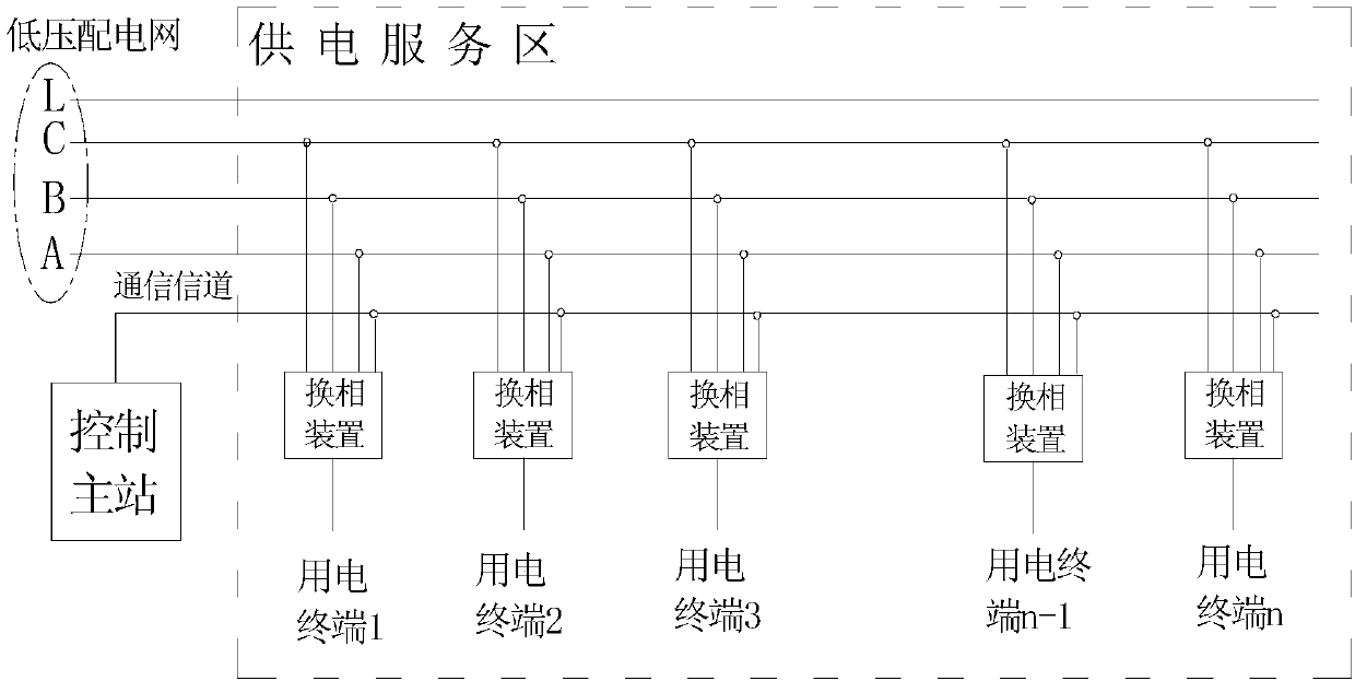
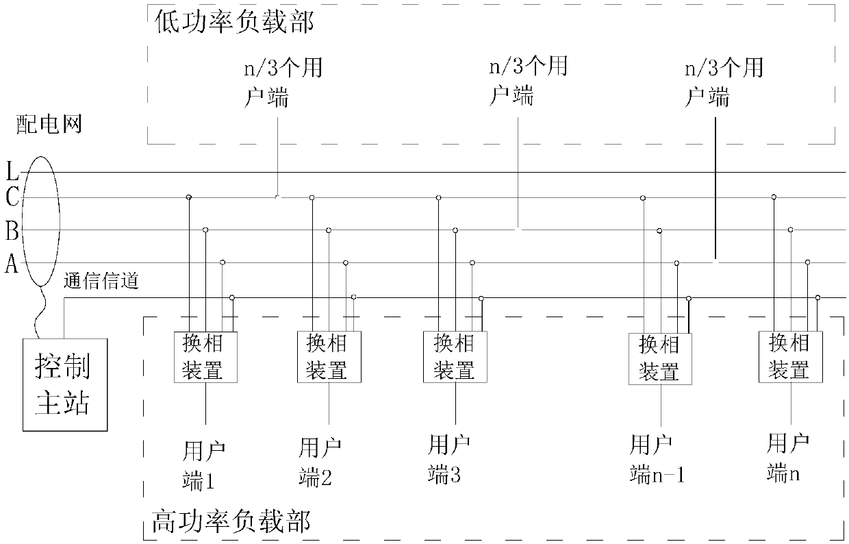
[0030] A method for connecting a power load to a power distribution network in this embodiment, such as figure 2 , image 3 As shown, the low-voltage output side of the distribution transformer (which can be understood as the distribution network) adopts a three-phase four-wire system and is wired to residential areas to provide electric energy to residential users. The power load of each residential user (referred to as the user end) is classified into a daily low power load part and a high power load part. The low-power load part mainly includes power consumption of low-power load devices such as daily lighting, refrigerators, washing machines, gas water heaters, and gas cookers, such as load devices with power ranging from tens of watts to two to three hundred watts. The low-power load part is directly connected to one of the phases of the distribution network, and evenly connected to the three phases of the distribution network according to the number of users. The numbe...

Embodiment approach 2

[0062] During the three-phase load balancing process of the distribution network, when the existing technology selects the phase commutation device that needs to be switched separately, it does not consider the difference in the type of the load device powered by the phase commutation device, resulting in built-in magnetic moving parts ( Such as the load device of the motor) produces commutation vibration, emits noise, and cannot run stably.

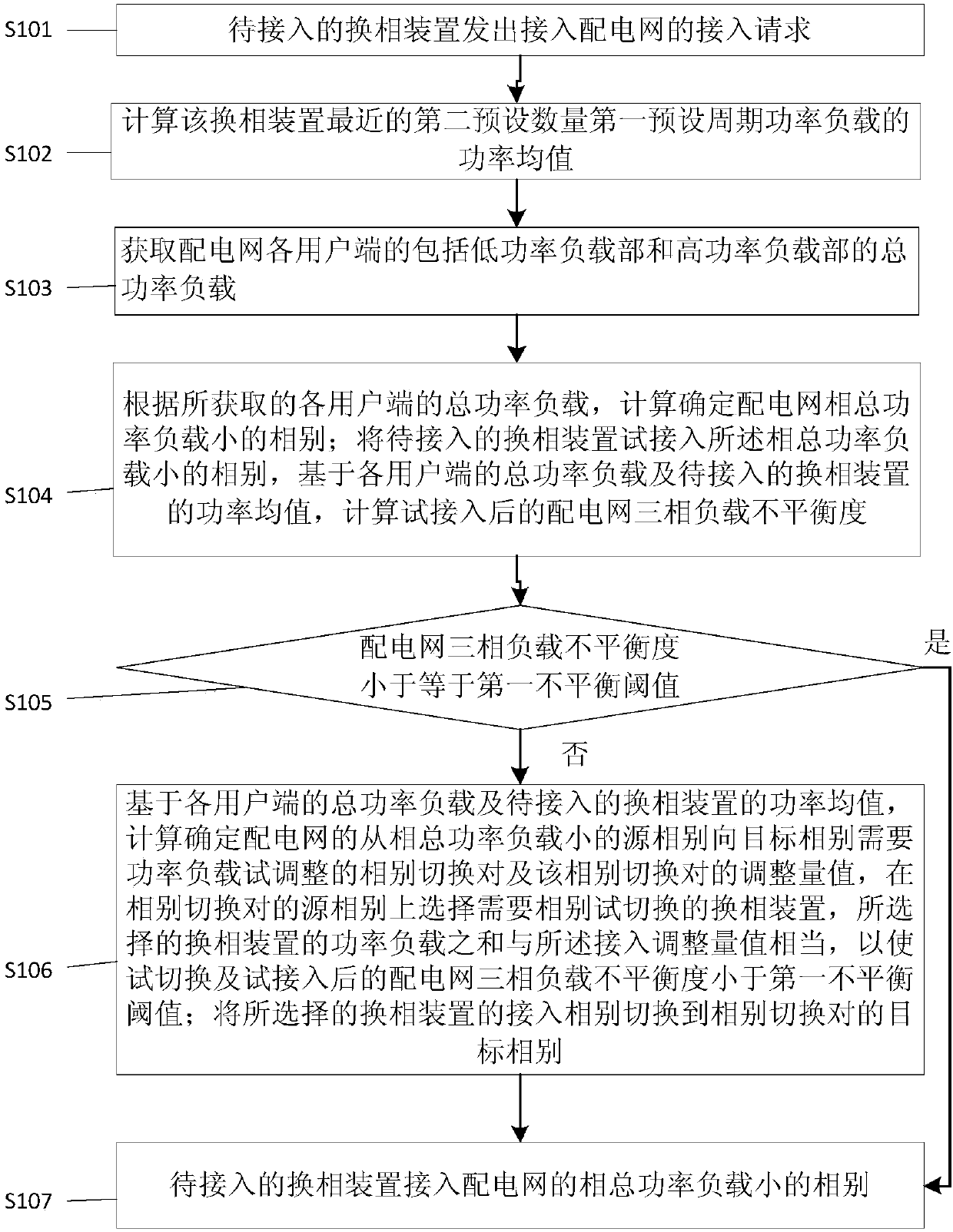
[0063] In order to overcome the above problems, this implementation mode provides a three-phase load balancing method for distribution network, the main design points of which are as follows: Figure 4 shown, including the following steps:

[0064] S201. Acquire the total power load of each user end including the low power load part and the high power load part; the total power load includes the power load value of the low power load part of the user end, the access phase difference, and the The power load value and access are different...

specific example 1

[0076] In order to enable those skilled in the art to better understand the technical solution of Embodiment 1 above, an application example is given below to further illustrate the method of how the above-mentioned commutation device to be connected is connected to the distribution network. The power load at each user end includes a low-power load part and a high-power load part. The low-power load part is directly connected to one of the phases of the distribution network and evenly distributed on the three-phase lines of the distribution network, such as image 3 As shown in Table 4, the high power load part is connected to one of the phases of the distribution network through the phase commutation device. For the convenience of description, take 12 user terminals as an example, the low-power load parts of the 12 user terminals are directly connected to the distribution network, and each phase line is respectively connected to the low-power load parts of 4 user terminals, as...


PUM


Abstract

The invention discloses a method for connecting a power load to a distribution network and a load balancing method. For the access method, before a power load of a user is connected to a distributionnetwork by a commutation device, calculation is carried out based on a commutation device trial access power estimation value and total power loads of all user terminals to determine the to-be-connected target phase, so that the three-phase loads of the distribution network are kept to be balanced. Therefore, the number of the commutation device of phase switching as well as the harmonic interference to the distribution network is reduced. In addition, according to the balancing method, the three-phase loads of the distribution network become unbalanced and a phase switching pair and an adjusting amount value are determined; commutation devices, not providing power for a built-in magnetic moving part load unit, of the source phase are marked; in terms of the source phase, the marked commutation device needing phase switching is selected; if the marked commutation devices are not enough, un-marked commutation devices are selected; and the phases of the selected commutation device are switched to the target phases, so that three-phase load balancing is realized. No commutation vibration is caused by the load device of the user terminal and thus the load device works stably.

Description

technical field [0001] The invention relates to a three-phase load balancing technology for a distribution network, in particular to a method for connecting power loads to a distribution network for a low-voltage distribution network, and a three-phase load balancing method for a low-voltage distribution network, belonging to Low-voltage distribution network power distribution technology field. Background technique [0002] The load of the distribution transformer in the distribution network is generally composed of a mixture of three-phase load and single-phase load. Residential electricity is all single-phase load, and the distribution network is relatively complicated, especially the distribution system where a large number of single-phase loads are connected to the low-voltage distribution network. , and the load size is different and the power consumption time is different. Therefore, the imbalance between the three phases of the low-voltage distribution network is irre...

Claims


Application Information

Patent Timeline
Patent Type & Authority Applications(China)
IPC IPC(8): H02J3/14H02J3/26H02J3/24
CPCY02B70/3225Y02E40/50Y04S20/222
Inventor 陈鸽
Owner GUANGXI POWER GRID CORP
Why Eureka
Try Eureka