Unmanned ship

An unmanned ship and hull technology, applied in the direction of hull, ship construction, hull parts, etc., can solve the problems of easy jamming, large labor, high design cost, etc., and achieve the effect of avoiding jamming

Pending Publication Date: 2018-01-19
陕西欧卡电子智能科技有限公司
View PDF10 Cites 15 Cited by
  • Summary
  • Abstract
  • Description
  • Claims
  • Application Information

AI Technical Summary

Problems solved by technology

The traditional manual cleaning method uses small manned water surface vehicles to reach the garbage on the water surface and manually cleans it with tools. This method requires a lot of labor, high cost, low efficiency, and low safety.
[0003] In the existing patent document "A Water Surface Cleaning Ship" (application number: 201220739860.3, application date: December 30, 2012, publication number: 203005707U, publication date: June 19, 2013), the cleaning ship includes The left ship and the right ship are connected by a bridge, and there is a trawling net between the two ships, which can achieve the purpose of cleaning the garbage on the surface of the water; in fact, the trawling net in the cleaning ship is only suitable for wide waters, and the function of the cleaning ship is single
In the patent document "A Water Cleaning Boat" (application number: 201310458010.5, application date: March 19, 2015, publication number: 103466049A, publication date: December 25, 2013), the stern of the cleaning boat is provided with a propulsion device , the bow is equipped with a cleaning hatch and a mechanical arm, and the hull is equipped with a wireless control device, a cleaning motor, a clearing m

Method used


Image

  • Unmanned ship
  • Unmanned ship

Examples


Embodiment Construction

[0020] The present invention will be described in detail below in conjunction with the accompanying drawings and specific embodiments.

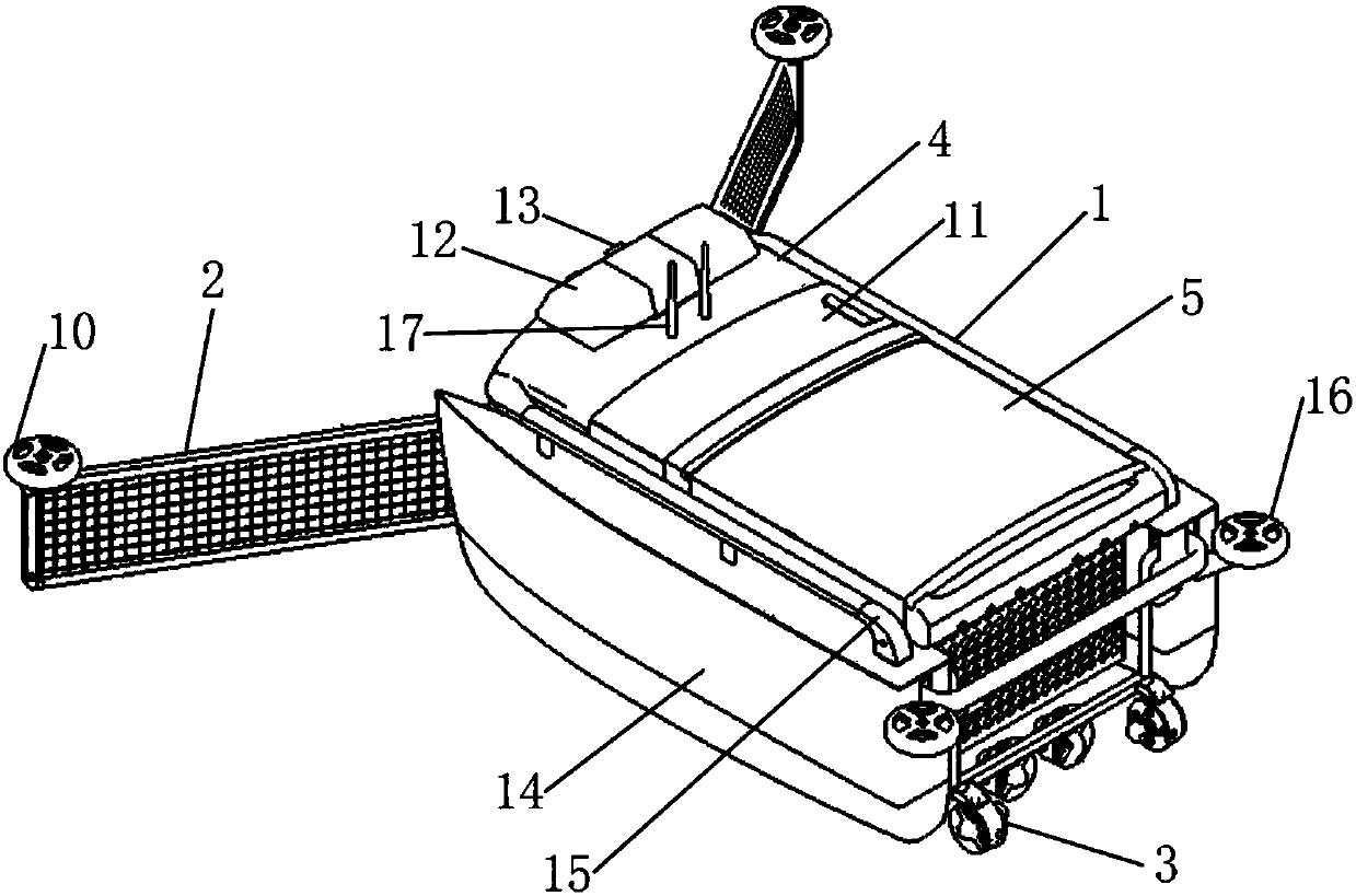
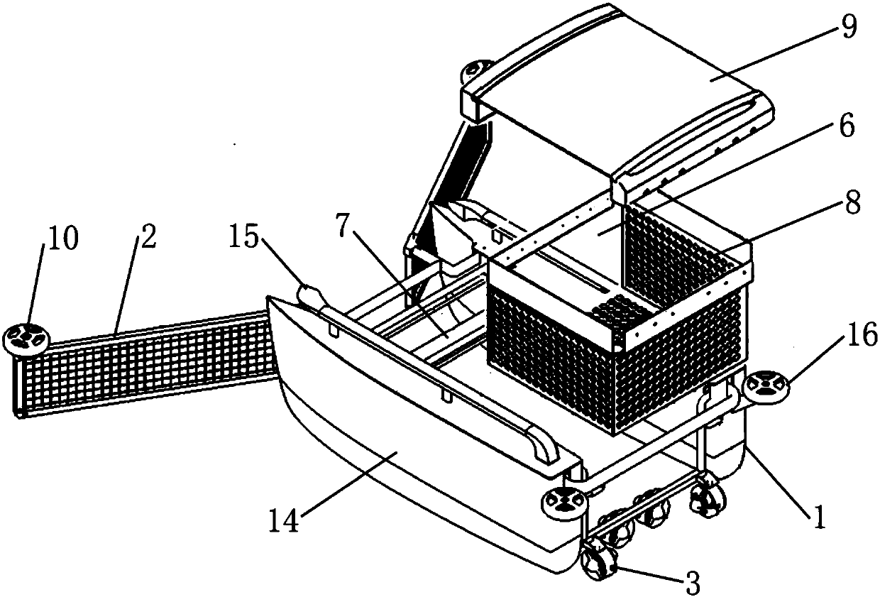
[0021] The invention provides an unmanned ship, such as figure 1 As shown, it includes a hull 1, the end of the hull 1 is provided with a guiding device 2, the tail of the hull 1 is provided with a propeller 3, and the hull 1 is provided with a control device 4 and a garbage collection device 5 connected in a detachable manner. The garbage collection device 5 is dismounted and arranged on the hull 1, and the garbage collection device 5 can be disassembled to clean up the garbage when the garbage collection is full.

[0022] The control device 4 includes a central processing unit, and the central processing unit is respectively connected with a video acquisition unit, a motor control unit and a wireless communication module; the motor control unit is connected with the thruster 3 through wires; the base station arranged on the ground communica...


PUM


Abstract

The invention discloses an unmanned ship. The unmanned ship comprises a hull, wherein guiding devices are respectively arranged at the end part of the hull; propellers are arranged at the tail of thehull; a control device and a rubbish collecting device which is connected in a disassembling type are arranged on the hull; and a warning light is arranged at the top surface of the control device. According to the unmanned ship disclosed by the invention, information of a water surface is collected by a video acquiring unit, and the collected information is sent to a central processing unit of the control device; a base station on the ground communicates with the central processing unit through a wireless manner; the central processing unit is used for sending the video information acquired by the video acquiring unit to the base station; an operator sends a control signal to the central processing unit through the base station; the propellers are controlled by the central processing unitthrough a motor control unit to drive the hull to move, so that autonomous navigation and a water surface cleaning task are performed; and the locking and the collision of the unmanned ship in a water region edge zone can be avoided by a rotating wheel on a navigation device and guide wheels arranged at the upper end of the tail of the hull, so that the unmanned ship can clean sundries on the water surface of any region.

Description

technical field [0001] The invention belongs to the field of unmanned equipment and relates to an unmanned ship. Background technique [0002] The cleaning of water surface garbage in water areas (such as lakes, reservoirs, etc.) is often performed by many water conservancy facilities. The traditional manual cleaning method uses small manned water surface vehicles to reach the surface garbage location and manually cleans it with tools. This method is labor-intensive, high in cost, low in efficiency, and low in safety. [0003] In the existing patent document "A Water Surface Cleaning Ship" (application number: 201220739860.3, application date: December 30, 2012, publication number: 203005707U, publication date: June 19, 2013), the cleaning ship includes The left ship and the right ship are connected by a bridge, and there is a trawling net between the two ships, which can achieve the purpose of cleaning the garbage on the surface of the water; in fact, the trawling net in t...

Claims


Application Information

Patent Timeline
IPC IPC(8): B63B35/32B63B45/00B63B3/14G08C17/02H04N5/232
Inventor 孙斌王哲朱健楠马申宇郭萌睿刘博
Owner 陕西欧卡电子智能科技有限公司
Why Eureka
Try Eureka