Variable valve timing device

A valve timing, variable technology, used in valve devices, non-mechanically actuated valves, engine components, etc., to solve problems such as oil leakage and difficult parts processing

Inactive Publication Date: 2018-01-19
陆逸钧
View PDF6 Cites 0 Cited by
  • Summary
  • Abstract
  • Description
  • Claims
  • Application Information

AI Technical Summary

Problems solved by technology

Most of the valve timing control devices on the market today use electro-hydraulic ...

Method used


Image

  • Variable valve timing device
  • Variable valve timing device

Examples


Embodiment Construction

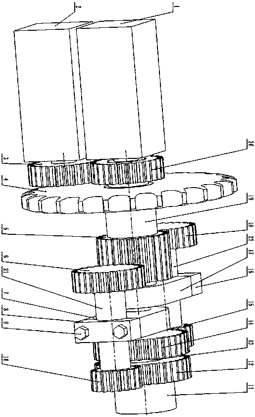
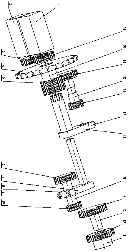
[0006] The upper sprocket (4), the driving gear (5), the connecting shaft (19) and the servo motor (1), the first arm, the first countershaft (21), the first countershaft gear (6, 10), the first countershaft The first set of control group consisting of a driven gear (12) can control the phase of the camshaft (11); add servo motor (2), gear shaft (3), gear (20), second arm, second middle The second set of control group composed of the shaft (22), the second countershaft gears (18, 15) and the second driven gear (14) can control the phase of the second shaft (13) rotating around the camshaft axis. The upper sprocket (4) and the driving gear (5) are fixed on the connecting shaft (19) or the upper sprocket (4) is integrally processed with the driving gear (5) and the connecting shaft (19); the connecting shaft (19) relies on the bearing It is positioned on the fixed mount and rotates around the axis of the camshaft (11); the axis of the connecting shaft (19) is drilled with a thro...


PUM


Abstract

The invention discloses a variable valve timing device. A driven gear is fixed at one end of a camshaft; an upper chain wheel is arranged on one side of the camshaft; the upper chain wheel and a driving gear are fixed to a connecting shaft; the connecting shaft is located on a fixing bracket depending on a bearing, and rotates around the axis of the camshaft; a through hole is drilled in the axisof the connecting shaft; an arm consists of a big end, a small end and screws; the big end of the arm consists of a cylinder and a long block extending in the radial direction of the cylinder; two gears different in reference diameters are fixed to a middle shaft; a section of narrow neck is formed in the middle shaft; two semicircular concave surfaces of the big end and the small end of the arm are clamped in the narrow neck; the big end can be connected with the small end through the screws; and two middle shaft gears are correctly engaged with the driving gear and the driven gear correspondingly. A cylinder of a driving arm controlled by servo motors rotates around the axis of the camshaft, and the position of the middle shaft is changed, so that the phase relation between an input gearand an output gear is changed, and valve timing is changed. By additionally adopting a servo motor, an arm, a middle shaft, middle shaft gears, a driven gear and a transmission gear, the phase of a second shaft rotating around the axis of the camshaft can be controlled.

Description

technical field [0001] The invention relates to the field of internal combustion engine valve timing control. Background technique [0002] In order to increase the torque at each speed of the internal combustion engine, the variable valve technology has appeared and developed for more than ten years. Most of the valve timing control devices on the market today use electro-hydraulic control technology, which has the problems of difficult parts processing and oil leakage. Contents of the invention [0003] The servo motor controls the position of the intermediate shaft, changes the phase relationship of the input and output gears, thereby adjusting the phase of the camshaft, and optimizes the transmission ratio between the sprockets to reduce chain vibration. The device is mainly a gear mechanism with simple control and no problem of oil leakage. Description of drawings [0004] figure 1 Assembly drawing [0005] figure 2 exploded diagram. detailed description ...

Claims


Application Information

Patent Timeline
IPC IPC(8): F01L1/344F01L9/04
Inventor 陆逸钧
Owner 陆逸钧
Why Eureka
Try Eureka