Supercharge Your Innovation With Domain-Expert AI Agents!

Centrifugal blower

A centrifugal fan and fan technology, which is used in mechanical equipment, machines/engines, liquid fuel engines, etc., can solve the problems of not meeting the needs of clean and pollution-free, large fan equipment, energy loss and noise, etc., to meet the needs of clean and pollution-free. , The effect of compact structure and low energy loss

Pending Publication Date: 2018-01-19
潍坊富源增压器有限公司
View PDF10 Cites 1 Cited by
  • Summary
  • Abstract
  • Description
  • Claims
  • Application Information

AI Technical Summary

Problems solved by technology

[0003] The traditional centrifugal fan is used in the way of gear acceleration. For example, the authorized announcement number is CN202007882U, and the Chinese utility model patent named centrifugal fan speed-up gearbox requires gear speed-up transmission mechanism, conventional bearing support and oil lubrication system. , the problem of this traditional centrifugal fan is: on the one hand, due to the use of lubricating oil to lubricate the mechanical friction pair, the air output by the fan is oily, which cannot meet the clean and pollution-free needs of special industries such as food, medicine, and electronics; On the other hand, since the power output by the ordinary motor needs to be transmitted to the impeller through the gear speed-up transmission mechanism, during the power transmission process, there will be huge energy loss and noise due to mechanical friction, and the setting of the speed-up gearbox will cause the entire set of The fan equipment is bulky and takes up a lot of space

Method used


Image

  • Centrifugal blower

Examples


Embodiment Construction

[0020] The present invention will be described in further non-limiting detail below in conjunction with the accompanying drawings and examples.

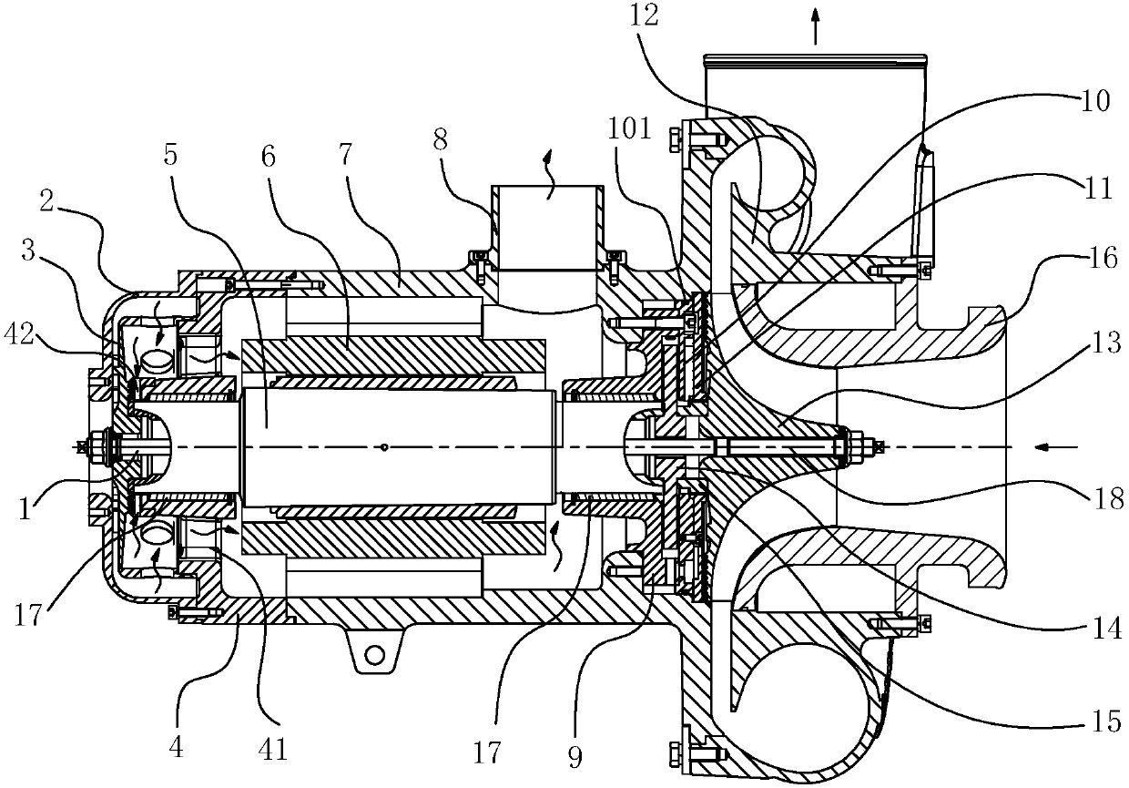
[0021] For the convenience of description, in this paper, the end face of the component away from the center of the main shaft is defined as the outer end face, and the end face close to the center of the main shaft is defined as the inner end face; the terms "first", "second", etc. are only used for description purposes and cannot be understood as indicate or imply relative importance; figure 1 In , the straight arrow indicates the flow direction of the delivered gas, and the curved arrow indicates the air flow direction.

[0022] Such as figure 1 As shown, the centrifugal fan in the embodiment of the present invention includes: a motor 6, a fan 3 driven by the motor 6 and an impeller 13, the impeller 13 is arranged in the compressor housing 12, and the fan 3 is provided with a fan cover 2, and the motor 6 is preferably a permanent...


PUM


Abstract

The invention discloses a centrifugal blower. The centrifugal blower comprises a fan and a impeller which are driven by a motor; the motor comprises a spindle arranged in a motor casing; one end of the spindle is directly connected with the fan, and the second end of the spindle is directly connected with the impeller; and air bearings are mounted at spindle necks at the two ends of the spindle correspondingly. According to the centrifugal blower, the motor directly drives the fan and the impeller, so that a traditional gear speed-increasing transmission mechanism is omitted; the whole centrifugal blower is compact in structure, small in size, low in energy loss and low in noise; the air bearings are mounted at the spindle necks at the two ends of the spindle correspondingly, air is used as a lubricating agent and a cooling agent, thus, an extra lubricating oil system is not needed, and output non-oily gas is clear, so that the clean and non-pollution requirements of the special industries such as the food industry, the medicine industry and the electronic industry are met; and the rotating spindle and the static air bearings do not make mechanical contact, so that abrasion is avoided, high efficiency and energy saving are achieved, noise is low, operation is reliable, maintenance is not needed for a long time, and the service life of the blower is long.

Description

technical field [0001] The invention relates to the technical field of fans, in particular to a centrifugal fan. Background technique [0002] Centrifugal fan is a machine that relies on input mechanical energy to increase gas pressure and transport gas. Centrifugal fan is widely used in ventilation, dust removal and cooling of factories, mines, tunnels, cooling towers, vehicles, ships and buildings; boilers and industrial furnaces Ventilation and air induction; cooling and ventilation in air conditioning equipment and household electrical appliances; drying and selection of grains, etc.; during work, the compressor impeller is driven by an ordinary motor, and the airflow enters the blade space axially from the fan, at high speed Under the action of the rotating impeller, on the one hand, it rotates with the impeller, on the other hand, it increases the energy under the action of inertia, leaves the impeller along the radial direction, and does work by the centrifugal force ...

Claims


Application Information

Patent Timeline
IPC IPC(8): F04D25/06F04D25/08F04D29/057F04D29/58
Inventor 陈良陈序尧刘风虎王新明刘伟王亮许全亮
Owner 潍坊富源增压器有限公司
Features
  • R&D
  • Intellectual Property
  • Life Sciences
  • Materials
  • Tech Scout
  • Unparalleled Data Quality
  • Higher Quality Content
  • 60% Fewer Hallucinations
Learn More