An optical phase contrast imaging system, method and computer readable medium

An optical phase and imaging method technology, applied in scientific instruments, instruments, measuring devices, etc., can solve problems such as long data collection time, physical information errors of the object to be measured, and impact on the imaging accuracy of the object to be measured, so as to reduce production requirements , avoid information errors, and save data collection time

Active Publication Date: 2021-06-25
SHANGHAI UNITED IMAGING HEALTHCARE
View PDF5 Cites 0 Cited by
  • Summary
  • Abstract
  • Description
  • Claims
  • Application Information

AI Technical Summary

Problems solved by technology

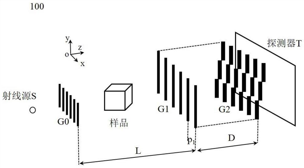
[0005] Aiming at the above-mentioned grating phase-contrast imaging process, it is necessary to use the stepping method to collect data, the data collection time is long, and the physical information error of the object to be measured is determined by the traditional method for the mechanical error of the echelle grating. This application proposes a The optical phase contrast imaging method and system solve the problem that the mechanical error caused in the echelle grating manufacturing process affects the imaging accuracy of the object to be measured

Method used


Image

  • An optical phase contrast imaging system, method and computer readable medium
  • An optical phase contrast imaging system, method and computer readable medium
  • An optical phase contrast imaging system, method and computer readable medium

Examples


Embodiment

[0067] Figure 7 According to some embodiments of the present application, it is a comparison chart of the light intensity change curve obtained by using the optical phase contrast imaging method using the fitting method disclosed in the present application and the traditional cosine method and the original data. Wherein, the abscissa is the offset between the echelle grating units, and the ordinate is the received X-ray intensity value. Among them, the curve indicated by * is the original data, and the black curve is the step curve obtained by the traditional cosine method. The lighter-colored line in the figure is the light intensity change curve obtained by using the echelon grating information processing method with any step size described in this application.

[0068] From Figure 7 It can be seen from the figure that the light intensity change curve obtained by the fitting algorithm with any step size proposed by this application is closer to the original data than the...


PUM


Abstract

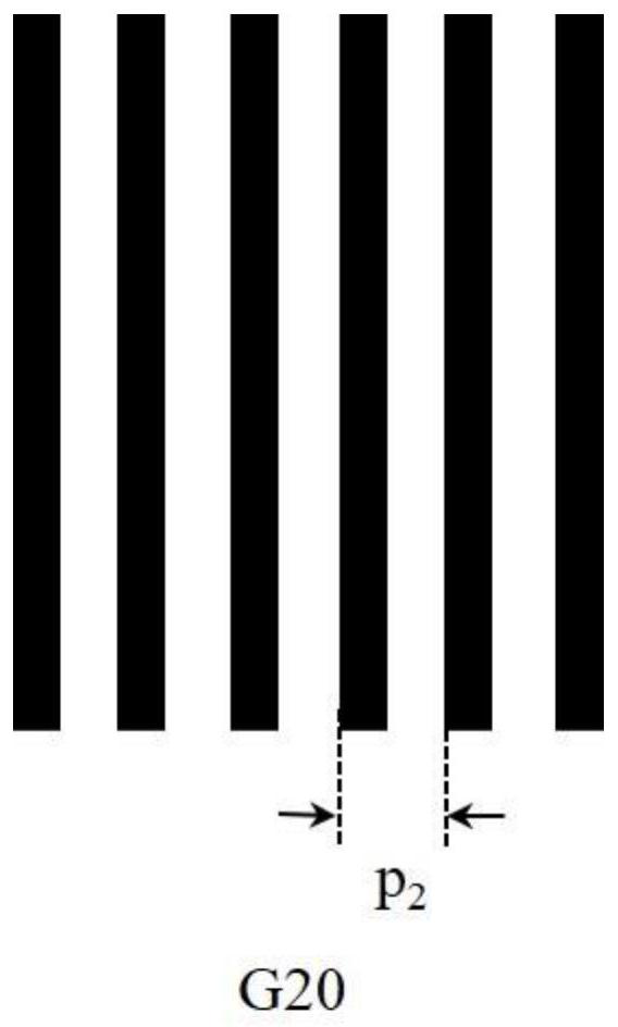
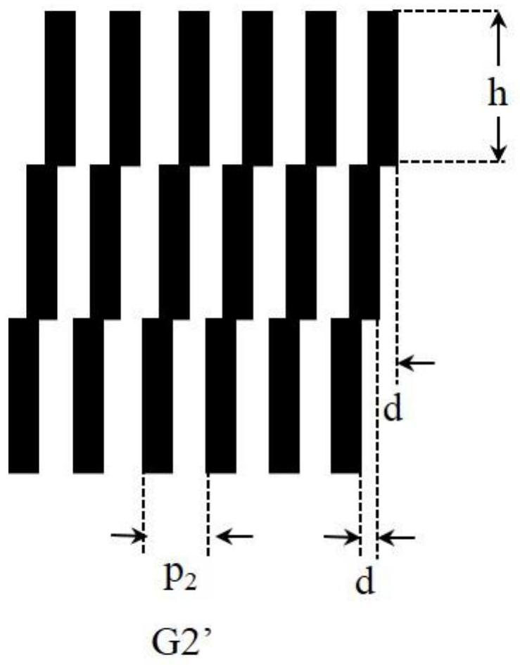
The present application relates to an optical phase contrast imaging method and system. The optical phase contrast imaging method includes: acquiring a first light intensity value measured by a detector unit group after rays pass through the echelon grating block when there is an object to be measured; according to the first light intensity value, based on a fitting algorithm, determining at least one first parameter value used to characterize the first light intensity change curve when the object to be measured exists; acquiring the second light detected by the detector unit group after the ray passes through the echelon grating block when the object to be measured does not exist Intensity value; according to the second light intensity value, based on a fitting algorithm, determine at least one second parameter value for characterizing the second light intensity change curve when there is no object to be measured; based on the at least one first parameter value and at least one second parameter value to determine at least one physical information of the object to be measured.

Description

technical field [0001] The present application relates to the field of grating phase contrast imaging, in particular to an echelle grating optical phase contrast imaging system and method. Background technique [0002] X-ray phase contrast imaging technology uses the phase change when the ray passes through the object to be measured, that is, the phase shift, to form image contrast. Using ray phase contrast imaging technology can obtain higher image contrast than traditional ray absorption imaging technology. In X-ray grating phase contrast imaging, the phase stepping algorithm is usually used as the gold standard for separation of absorption, refraction and scattering information of the object to be measured. This method needs to step the grating at a certain projection angle with equal steps, usually four to eight Step by step, this method of mechanically stepping the grating greatly prolongs the data acquisition time and requires extremely high device stability in CT. ...

Claims


Application Information

Patent Timeline
Patent Type & Authority Patents(China)
IPC IPC(8): G01N23/041G01N23/06
Inventor 鲍园
Owner SHANGHAI UNITED IMAGING HEALTHCARE
Why Eureka
Try Eureka