
Improved control method of current-controlled inverter in microgrid

A current control and inverter technology, applied in the research field of inverter coordinated control

Active Publication Date: 2019-11-08
西安奇点能源股份有限公司
View PDF3 Cites 0 Cited by
  • Summary
  • Abstract
  • Description
  • Claims
  • Application Information

AI Technical Summary

Problems solved by technology

[0005] In order to overcome the problems existing in the traditional droop control method, the purpose of the present invention is to provide an improved control method for the current-controlled inverter in the microgrid, so as to make up for the defects of the voltage source of the traditional droop control and improve the overall operation performance of the parallel system

Method used


Image

  • Improved control method of current-controlled inverter in microgrid
  • Improved control method of current-controlled inverter in microgrid
  • Improved control method of current-controlled inverter in microgrid

Examples


Embodiment Construction

[0053] The present invention will be further described in detail below in conjunction with specific examples, which are explanations of the present invention rather than limitations.

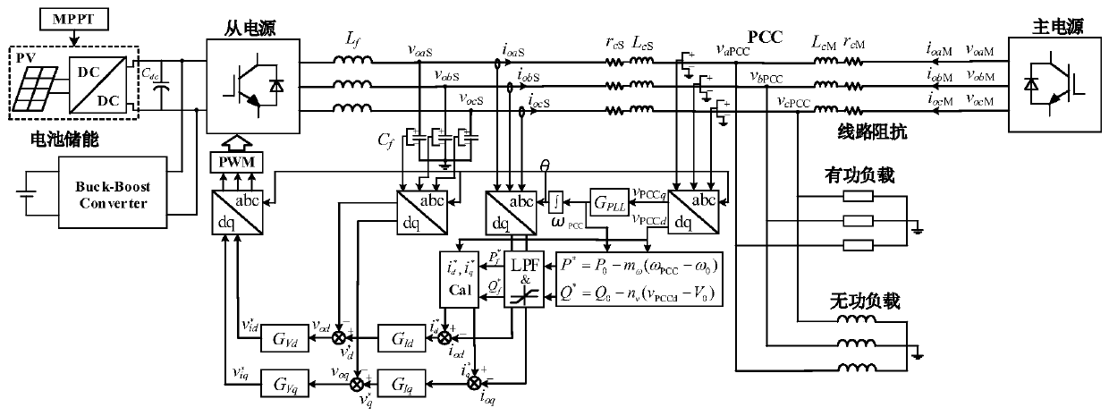
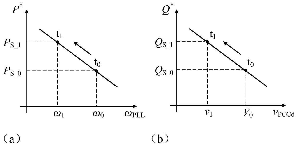
[0054] The invention provides an improved control method for a current-controlled inverter, the principle of which is as follows Figure 1 to Figure 3 shown. In the simulation, the improved method is compared with the inverter parallel system using the traditional control method, the results are as follows Figure 4 and Figure 5 shown. Figure 4 (a) and Figure 4 (b) shows the simulation waveform diagram of the output power of two parallel inverters controlled by the traditional method and the improved method when the resistive line impedance is used. It can be seen that the control method proposed by the present invention can also realize the equal sharing of active power under the condition of resistive line impedance, and will not cause huge reactive circulating current to damage the inv...


PUM


Abstract

The invention discloses a microgrid current control type inverter improved control method, and belongs to the research field of cooperative control of the inverter in the island microgrid. According to the method, a current control type inverter output power instruction control strategy is provided; the values of the output active power and reactive power of the inverter can be adjusted in real time by detecting the frequency and voltage amplitude change amount of a parallel inverter system in a point of common coupling, so as to realize uniform division of the active power among inverters ina steady state based on proportion; and a current source compensates reactive power output to assist to adjust the voltage at the load end. The method disclosed in the invention is high in reliabilityand feasibility, the operation performance of the island parallel inverter system is improved, and quite high reference value is provided for engineering application.

Description

technical field [0001] The invention belongs to the research field of coordinated control of inverters in island microgrids, and in particular relates to an improved control method for current-controlled inverters in microgrids. Background technique [0002] With the intensification of the energy crisis and the increasing burden on the environment from the use of traditional energy, the introduction of renewable energy has become an important means to alleviate the energy crisis and improve the quality of the environment. Due to the distribution and power randomness of renewable energy, the concept of microgrid is proposed to integrate and control the conversion, use and transmission of renewable energy. The distributed generation units connected in parallel in the microgrid are often connected to the common connection point with the AC bus through power electronic interfaces such as inverters. Generally speaking, the microgrid is connected to the public large grid through ...

Claims


Application Information

Patent Timeline
Patent Type & Authority Patents(China)
IPC IPC(8): H02J3/38H02M7/48
Inventor 刘进军王施珂刘增
Owner 西安奇点能源股份有限公司
Learn More