Power transmission linebird repelling device
A technology for power transmission lines and bird repelling, which can be used in overhead lines/cable equipment, electrical components, transmission systems, etc.
- Summary
- Abstract
- Description
- Claims
- Application Information
AI Technical Summary
Problems solved by technology
Method used
Image

Examples
Embodiment 1
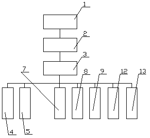
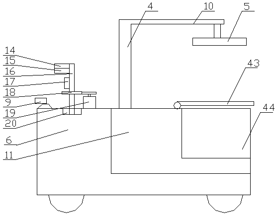
[0034] Embodiment one, such as figure 1 with figure 2 As shown, the present invention provides a transmission line bird repelling device, including a patrol car 6, a radar detection module 7, an ultrasonic bird repelling module 8 and a first camera 9 are arranged on the patrol car 6, and the patrol car 6. A carriage 11 is arranged at the rear, and a hoisting mechanism 4 is set on the carriage 11. The top of the hoisting mechanism 4 is rotated to set a crossbar 10, and the end of the crossbar 10 is provided with a cleaning mechanism 5 for processing bird's nests. The rear portion of the compartment 11 is provided with several accommodation cavities 44 for collecting bird's nests, and the above compartment 11 is provided with a protection plate 43 corresponding to the rotation of the accommodation cavities 44. The radar detection module 7, the ultrasonic bird repelling module 8, the first The camera 9 , the lifting mechanism 4 , and the cleaning mechanism 5 are connected to th...
Embodiment 2
[0038] Such as figure 1 with figure 2 As shown, the difference between this embodiment and Embodiment 1 is:
[0039] The radar detection module 7 and the ultrasonic bird repelling module 8 are arranged on the inspection trolley 6 through a rotating mechanism, and the rotation mechanism includes a rotating base 20 provided on the inspection trolley 6, and the rotating base 20 A rotating rod 16 is arranged on the top, the radar detection module 7 is arranged on the top of the rotating rod 16, the ultrasonic bird repelling module 8 is arranged in the middle of the rotating rod 16, and the lower part of the rotating rod 16 is connected with the transmission gear 18 The drive motor 19 on the patrol trolley 6 is connected to the control module 3 .
[0040] The radar detection module 7 includes a radio wave transmitter 14 and a radio wave receiver 15 arranged on the top of the rotating rod 16 , and the radio wave transmitter 14 and radio wave receiver 15 are connected with the con...
Embodiment 3
[0048] Such as Figure 3 to Figure 5 As shown, the difference between this embodiment and Embodiment 1 is:
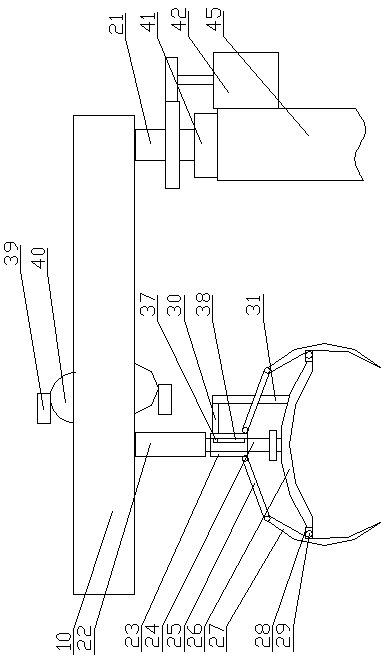
[0049] The lifting mechanism 4 adopts a hydraulic lifting column 45, and the top of the hydraulic lifting column 45 is provided with a mounting rod 21 through a pressure bearing 41. The cross bar 10 is arranged on the mounting rod 21, and the upper end of the hydraulic lifting column 45 is set The servo motor 42 that drives the installation rod 21 to rotate, the servo motor 42 is connected with the control module 3 .
[0050] The cleaning mechanism 5 includes a first telescopic mechanism 22 arranged below the cross bar 10, an extension rod 24 is arranged at the lower end of the first telescopic mechanism 22, and an arc-shaped cover body 26 with an opening downward is arranged at the lower end of the extension rod 24. A plurality of rotating brackets 28 are evenly distributed on the edge of the arc-shaped cover body 26, a rotating shaft 29 is arranged on the rotating brac...
PUM
 Abstract
Description
Claims
Application Information
 - R&D
- Intellectual Property
- Life Sciences
- Materials
- Tech Scout
- Unparalleled Data Quality
- Higher Quality Content
- 60% Fewer Hallucinations
Browse by: Latest US Patents, China's latest patents, Technical Efficacy Thesaurus, Application Domain, Technology Topic, Popular Technical Reports.
© 2025 PatSnap. All rights reserved.Legal|Privacy policy|Modern Slavery Act Transparency Statement|Sitemap|About US| Contact US: help@patsnap.com