
+/- 800 kV convertor station direct-current field high-voltage equipment mounting structure

A technology for high-voltage equipment and installation structures, applied in infrastructure engineering, construction, etc., can solve the problems of poor seismic performance of electrical equipment, reduce seismic performance, and affect power transmission, etc., achieve excellent seismic performance, reduce construction costs, and reduce land use. area effect

Active Publication Date: 2018-01-23
SOUTHWEST ELECTRIC POWER DESIGN INST OF CHINA POWER ENG CONSULTING GROUP CORP +1
View PDF9 Cites 0 Cited by
  • Summary
  • Abstract
  • Description
  • Claims
  • Application Information

AI Technical Summary

Problems solved by technology

Therefore, if the rigidity of the civil structure and related equipment supports used for electrical equipment installation is insufficient, its seismic performance will inevitably be reduced, resulting in poor seismic performance of electrical equipment, which cannot well meet the normal operating conditions of electrical equipment, especially It cannot meet the normal operation of electrical equipment when the earthquake intensity is 9 degrees, which seriously affects the normal power transmission
In addition, the installation of high-voltage equipment in the DC field of the ±800kV converter station also requires a certain amount of land resources. Therefore, how to save the land resources occupied by the DC field of the ±800kV converter station to the greatest extent and ensure the safe operation of all electrical equipment , is also a question that must be considered

Method used


Image

  • +/- 800 kV convertor station direct-current field high-voltage equipment mounting structure
  • +/- 800 kV convertor station direct-current field high-voltage equipment mounting structure
  • +/- 800 kV convertor station direct-current field high-voltage equipment mounting structure

Examples


Embodiment Construction

[0029] In order to make the object, technical solution and advantages of the present invention clearer, the present invention will be described in detail below in conjunction with the accompanying drawings and specific embodiments. It should be understood that the specific embodiments described here are only used to explain the present invention, not to limit the present invention.

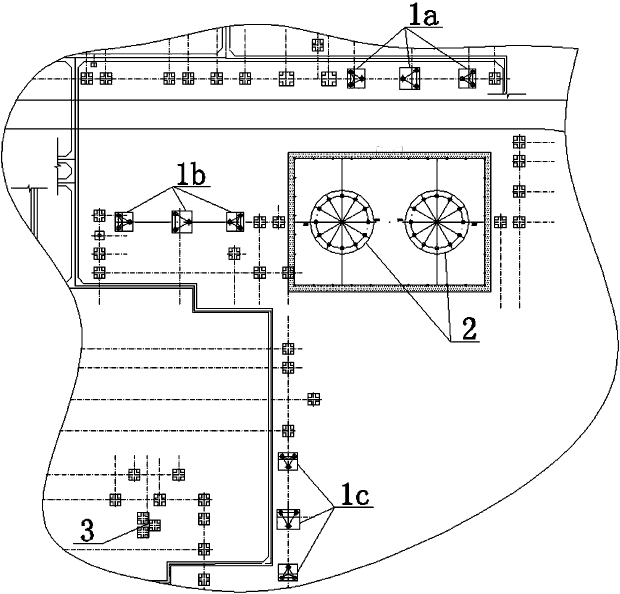
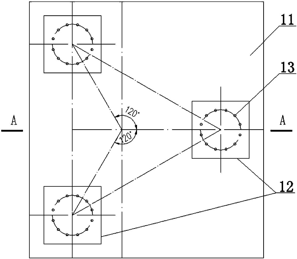
[0030] Such as figure 1 A ±800kV converter station DC field high-voltage equipment installation structure shown mainly includes 800kV grounding isolation switch foundation 1, high-voltage smoothing reactor foundation 2 and 800kV coupling capacitor support structure 3, and the 800kV grounding isolation switch foundation 1 includes 800kV ungrounded isolating switch foundation 1a, 800kV single-grounded isolating switch foundation 1b and 800kV double-grounded isolating switch foundation 1c. Among them, the 800kV ungrounded isolating switch foundation 1a, the 800kV single-grounded isolating switch fou...


PUM


Abstract

The invention provides a + / - 800 kV convertor station direct-current field high-voltage equipment mounting structure. The + / - 800 kV convertor station direct-current field high-voltage equipment mounting structure comprises a 800 kV grounded isolating switch base, high-voltage smoothing reactor bases and a 800 kV coupling capacitor bracket structure, wherein the 800 kV grounded isolating switch base comprises 800 kV ungrounded isolating switch bases, 800 kV single-point grounded isolating switch bases and 800 kV double-point grounded isolating switch bases; the 800 kV ungrounded isolating switch bases, the 800 kV single-point grounded isolating switch bases and the 800 kV double-point grounded isolating switch bases are distributed according to a V-shaped structure of which the opening faces the right; the high-voltage smoothing reactor bases are arranged on the opening side of the right-opening V-shaped structure; and the 800 kV coupling capacitor bracket structure is arranged parallel to the 800 kV double-point grounded isolating switch bases. By adoption of the + / - 800 kV convertor station direct-current field high-voltage equipment mounting structure provided by the invention,the excellent anti-seismic property of each electrical loop during a high-intensity earthquake can be ensured, the equipment bracket column top displacement acceleration amplification coefficient canmet the requirements of anti-seismic specifications for electric power facilities, and then the normal running requirements of electrical equipment can be met. Through the optimization of the direct-current field layout, the occupied land area can be reduced, and the safe distance can be kept after the electrical equipment is mounted in place.

Description

technical field [0001] The invention relates to the technical field of high-voltage equipment installation in a DC field of a ±800kV converter station, in particular to an installation structure for high-voltage equipment in a DC field of a ±800kV converter station. Background technique [0002] In the field of UHV DC transmission in electric power engineering, the requirements for civil structures and equipment supports are very high. The installation of the high-voltage equipment in the DC field of the ±800kV converter station requires the civil structure to cooperate with the equipment support, and the electrical equipment is installed on the top of the equipment support. When an earthquake occurs, the equipment support can amplify the displacement and acceleration of the electrical equipment installed on it. Therefore, if the rigidity of the civil structure and related equipment supports used for electrical equipment installation is insufficient, its seismic performance...

Claims


Application Information

Patent Timeline
Patent Type & Authority Applications(China)
IPC IPC(8): E02D27/44
CPCY02E60/60
Inventor 毛宇胡蓉彭清余波周德才杨关何勇冯仁德张朋朋
Owner SOUTHWEST ELECTRIC POWER DESIGN INST OF CHINA POWER ENG CONSULTING GROUP CORP
Learn More