Building thermal insulation wall

A technology for building thermal insulation and thermal insulation body, which is applied to buildings, building components, building materials, etc., can solve the problems of ineffective thermal insulation, inability to effectively block heat transfer, discontinuous thermal insulation materials, etc., to save the construction period, Eliminate fire hazards and have good fire protection effects

Pending Publication Date: 2018-01-23
湖州交科规划设计有限公司
View PDF4 Cites 1 Cited by
  • Summary
  • Abstract
  • Description
  • Claims
  • Application Information

AI Technical Summary

Problems solved by technology

The existing thermal insulation walls of buildings have the following technical problems: the thermal insulation material is inserted into the brick body, the gap is large and it is easy to fall, and the air convection between the upper and lower sides is easy to form, and a continuous phase is formed between the shells, and the thermal insulation material is scattered in it, which cannot Effectively cut off heat transfer, but cannot play an effective role in heat preservation; after the two bricks are combined, the heat preservation material is not continuous, and the heat insulation is basically ineffective

Method used


Image

  • Building thermal insulation wall
  • Building thermal insulation wall

Examples


Embodiment Construction

[0014] The present invention is not limited by the following examples, and specific implementation methods can be determined according to the technical solutions of the present invention and actual conditions.

[0015] Below in conjunction with embodiment and accompanying drawing, the present invention will be further described:

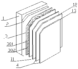
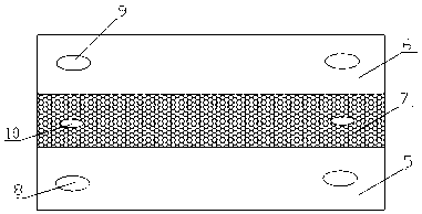
[0016] Such as figure 1 , 2 As shown, the thermal insulation wall of the building includes a foundation wall 1, a mortar leveling layer 2, an anti-crack protection layer 3 and a finish layer 4, and the foundation wall 1 is built by a plurality of composite thermal insulation bricks using a wall adhesive into; each composite heat insulating brick includes a first brick body 5, a second brick body 6 and an insulating body 7; the first brick body 5 and the second brick body 6 are rectangular parallelepiped bricks of the same size; the insulating body 7 It is a rectangular parallelepiped insulation board sandwiched between the first brick body 5 and th...


PUM


Abstract

The invention relates to the technical field of wall thermal insulation, in particular to a building thermal insulation wall. The building thermal insulation wall comprises a foundation wall, a mortarleveling layer, a thermal insulation layer, a crack resistant protective layer and a facing layer. The foundation wall is built by laying a plurality of composite type thermal insulation bricks by adopting a wall-building binding agent, each composite type thermal insulation brick comprises a first brick body, a second brick body and a thermal insulation body, and the first brick body and the second brick body are cuboid bricks with the same size; and the thermal insulation body is a cuboid thermal insulation plate arranged between the first brick body and the second brick body in a clamped mode, the two wide side faces of the thermal insulation body are in contact with one wide side faces of the first brick body and the second brick body correspondingly, the areas of the two wide side faces of the thermal insulation body are the same as the areas of the wide side faces of the first brick body and the second brick body, and therefore the first brick body, the thermal insulation body and the second brick body form a cuboid brick blank. According to the building thermal insulation wall, the living comfort degree is increased, because brick bodies on the two sides adopt inorganic building materials, the fireproof effect is excellent, if the thermal insulation body adopts a fireproof type material, the fireproof effect is better, and fire hazards can be effectively and completelyeradicated.

Description

technical field [0001] The invention relates to the technical field of wall insulation, in particular to a building insulation wall. Background technique [0002] Building walls need energy saving and heat preservation, which is an inevitable requirement to adapt to the development of modern construction industry and improve the living environment of people. In order to implement the country's industrial policy and promote the application of new energy-saving walls, a variety of technologies involving wall insulation have emerged in the industry. The most common is to coat a layer of insulation on the outer wall of the wall. The insulation layer is generally made of organic materials, which is not only not conducive to environmental protection, but also has common quality problems such as swelling, water seepage, water leakage, and falling off after a long time of use. [0003] At present, insulation bricks are also used to build walls in the industry. There are various typ...

Claims


Application Information

Patent Timeline
Patent Type & Authority Applications(China)
IPC IPC(8): E04B2/10E04C1/40E04B1/94
Inventor 张吉祥
Owner 湖州交科规划设计有限公司
Why Eureka
Try Eureka