Fabricated concrete variable section T-shaped shear wall component and construction method thereof

A technology of variable cross-section and concrete, which is applied in the direction of building components, walls, building structures, etc. It can solve the problem of weak sleeve connection, difficulty in staggering horizontal steel bar joints, and failure of steel bar skeletons in T-shaped shear wall components, etc. question

Active Publication Date: 2018-01-23
姚伟华 +1
View PDF12 Cites 0 Cited by
  • Summary
  • Abstract
  • Description
  • Claims
  • Application Information

AI Technical Summary

Problems solved by technology

[0004] In order to overcome the deficiencies of the existing technology, it is difficult to stagger the horizontal reinforcement joints of a large number of cast-in-situ cast-in-place concrete variable-section T-shaped shear wall components at present, and the vertical reinforcement connection adopts sleeve connections that are not firm and inconvenient to operate. The quality is difficult to guarantee. T The reinforcement of the type shear wall member does not form the steel bar skeleton and other problems. The first purpose of the present invention is to provide a kind of prefabricated concrete variable section T-shaped shear wall component. By improving the prefabricated concrete variable section T-shaped shear wall component Structural design, by changing the cross-section of prefabricated reinforced concrete variable cross-section T-shaped shear wall members, the vertical steel bars protruding from the lower part of the upper part of the exposed members on both sides of the lower part of the exposed members, and the steel bar joints of the vertical rebars of the edge members, usi

Method used


Image

  • Fabricated concrete variable section T-shaped shear wall component and construction method thereof
  • Fabricated concrete variable section T-shaped shear wall component and construction method thereof
  • Fabricated concrete variable section T-shaped shear wall component and construction method thereof

Examples


Embodiment 1

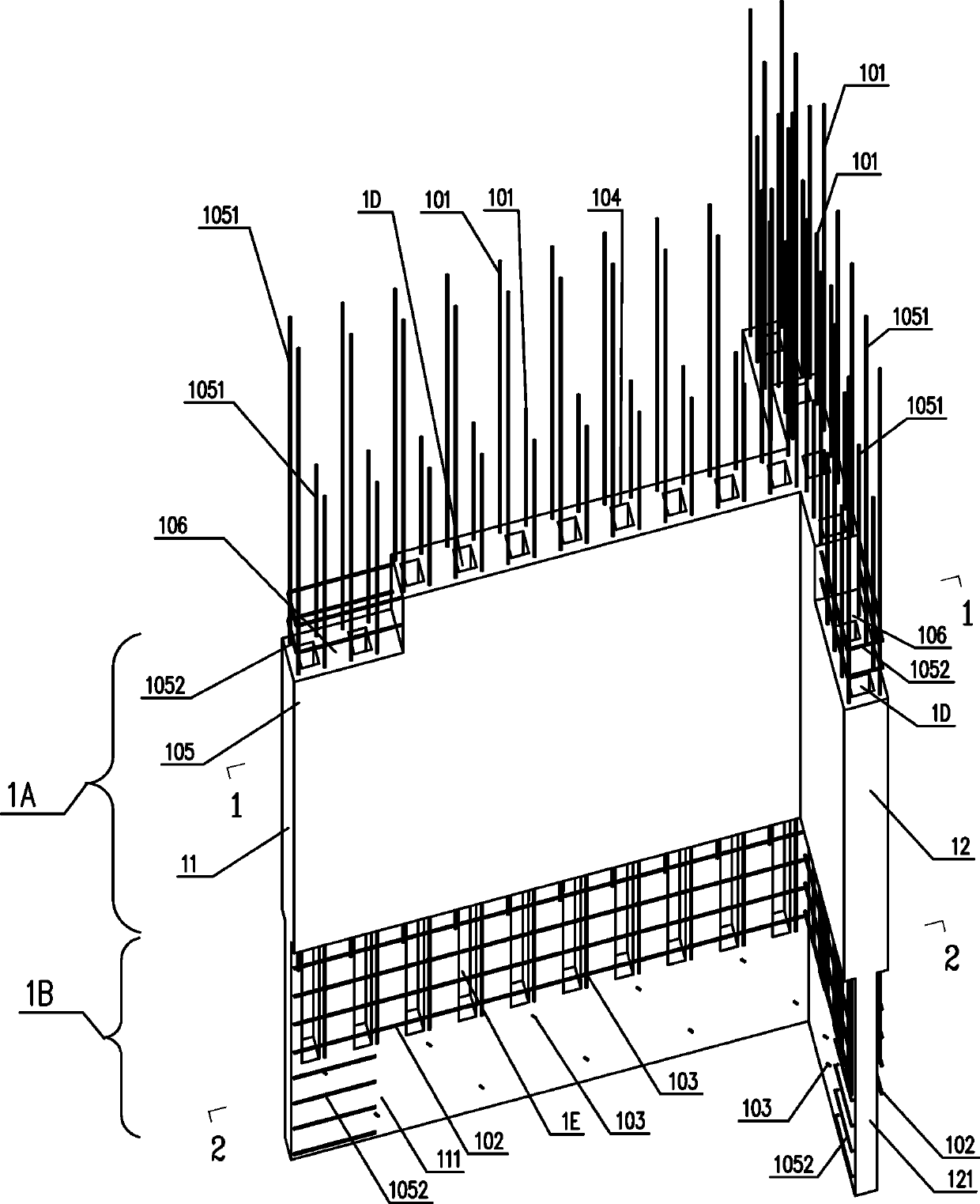
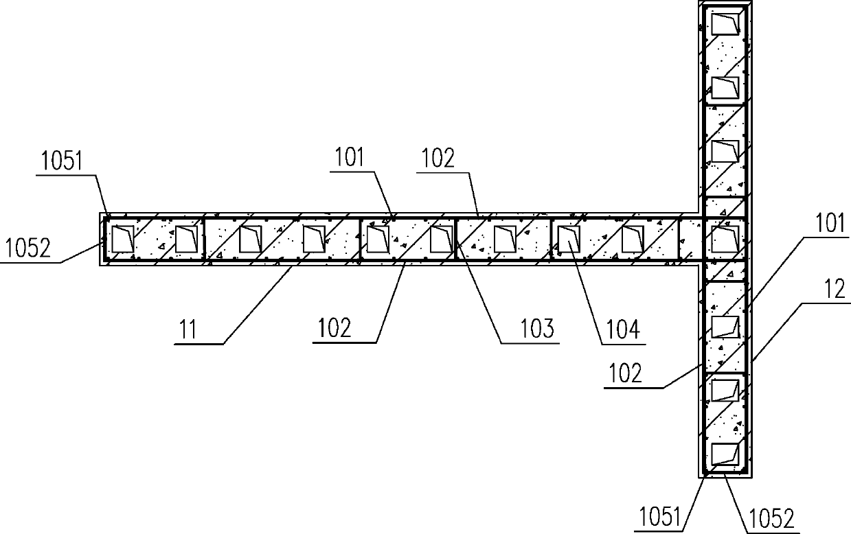
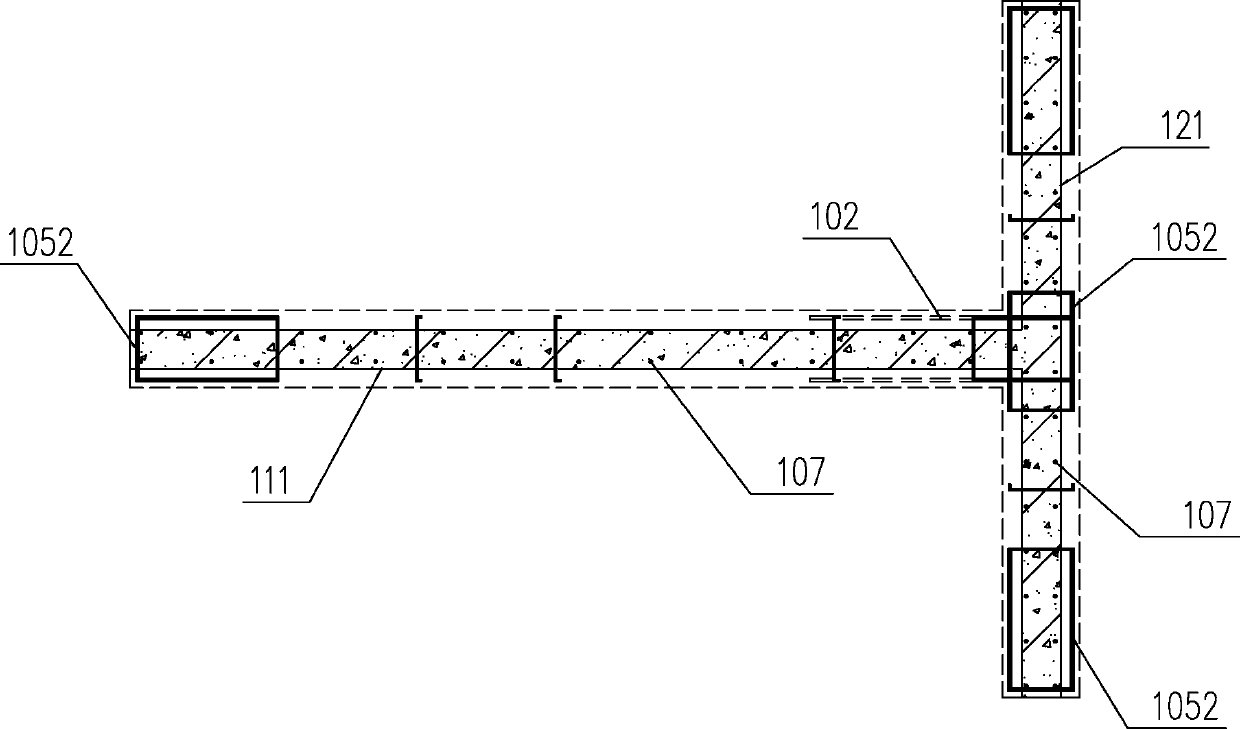
[0069] Such as Figure 1-3 As shown, a prefabricated concrete variable-section T-shaped shear wall member of the present invention includes an X-direction wall pier 11 and a Y-direction wall pier 12, and the X-direction wall pier 11 and the Y-direction wall pier 12 are wing walls, so The T-shaped shear wall member is divided into an upper part 1A of the member and a lower part 1B of the member formed by reducing the variable section, which is a whole formed by pouring concrete; the upper part 1A of the member is pre-embedded with vertical reinforcement 101, horizontal reinforcement 102 and tension Tie steel bars 103, the outer ends and intersections of the X-direction wall pier 11 and Y-direction wall pier 12 are provided with edge members 105, and the vertical reinforcement 101 in the edge member 105 is reinforced into the vertical reinforcement 1051 of the edge member, and installed There are stirrups 1052; the vertical reinforcement 101 and the edge member vertical reinforc...

Embodiment 2

[0071] Such as Figure 4-9 As shown, a manufacturing mold of a prefabricated concrete variable cross-section T-shaped shear wall member described in Example 1 of the present invention includes an X-direction wall pier mold 21, a Y-direction wall pier mold 22, and formwork diagonal supports 23 , pier 24 and Y-direction wall plinth oblique support 25; said X-direction wall pier mold 21 includes X-direction wall pier manufacturing platform 211, X-direction wall pier side formwork 212, X-direction wall pier top formwork 213, member lower section X-direction Wall core surface template 214, X-direction wall pier variable section baffle plate 215, X-direction wall pier bottom formwork 216, X-direction wall pier L-shaped connecting beam support template 217, vertical tunnel mold 201; the Y-direction wall pier The mold 22 includes a Y-direction wall pier making platform 221, a Y-direction wall pier side formwork 222, a Y-direction wall pier top formwork 223, a component lower section Y...

Embodiment 3

[0079] Such as Figure 4 with Figure 7As shown, a production mold of a prefabricated concrete variable-section T-shaped shear wall member described in Example 1 of the present invention is based on Example 2, on the Y-direction wall pier production platform 221 A movable rotating mechanism 203 with a clamping device is provided below. After the pouring process of the Y-direction wall 12 is completed and the mold is removed, the Y-direction wall 12 is fixed by the clamping device and moved to the maintenance process. Requirements, then move to the pouring process of the X-direction wall 11, rotate 90° along the X-direction wall 11, so that the X-direction wall 11 to be poured is in a horizontal state, and further erect the X-direction wall 11 related production molds, the X When the concrete part filled into the wall pier mold 21 communicates with the vertical tunnel 104 of the Y-direction wall pier 12, a vertical tunnel blocking formwork 204 is installed at the vertical tunn...


PUM


Abstract

The invention belongs to the technical field of building materials and building construction, and particularly relates to a fabricated concrete variable section T-shaped shear wall component and a manufacturing mold and a construction method thereof. The T-shaped shear wall component comprises an X-direction wall column (11) and a Y-direction wall column (12), and the X-direction wall column (11)and the Y-direction wall column (12) are mutually wing walls. The T-shaped shear wall component is divided into a component upper section (1A) and a component lower section (1B) which is formed by tapering the variable section, and a whole body formed by concrete pouring. Through the variable section, vertical rebars (101) on the two sides of the component lower section (1B) and a rebar joint (1C)of an edge component vertical rebar (1051) are exposed, and thus the problem that connection between a vertical rebar (101) of the T-shaped shear wall component and the edge component vertical rebar(1051) is insecure can be conveniently solved by adopting a welding connection method. By arranging a special vertical drill way (104) for cast-in-place concrete (32), the cast-in-place concrete (32)can be easy to pour and vibrate to be compact, and accordingly quality defects are avoided.

Description

technical field [0001] The invention belongs to the technical field of building materials and building construction, and relates to a shear wall component used for building structures, in particular to an assembled concrete variable-section T-shaped shear wall component, a manufacturing mold and a construction method thereof. Background technique [0002] Assembly building is to connect the same kind of prefabricated components or different kinds of prefabricated components. Since the reinforced concrete shear wall is integrated with concrete and steel bars, it is necessary to solve the connection problem of the longitudinal and vertical reinforcement of the shear wall, especially the shear wall. The connection problem of vertical reinforcement at the bottom. At present, the connection of vertical reinforcement at the bottom of prefabricated reinforced concrete variable cross-section T-shaped shear wall members mostly adopts the sleeve grouting method, and there are many prob...

Claims


Application Information

Patent Timeline
IPC IPC(8): E04B2/56B28B7/16E04G21/26
CPCY02E10/20
Inventor 姚芳辉姚伟华宋杨
Owner 姚伟华
Why Eureka
Try Eureka