
Transmission line iterative distance measuring method based on zero-mode traveling wave velocity variation characteristic

A technology of transmission line and distance measurement method, which is applied in directions such as fault locations, can solve the problems of difficult to achieve accurate positioning of long-distance transmission lines, inaccurate results of distance measurement, and difficult to achieve accurately, and achieves good use value, anti-interference and other problems. Powerful, fast-calculating effects

Active Publication Date: 2018-01-23
CHINA UNIV OF MINING & TECH
View PDF6 Cites 13 Cited by
  • Summary
  • Abstract
  • Description
  • Claims
  • Application Information

AI Technical Summary

Problems solved by technology

Compared with the traveling wave method, the sampling frequency of the impedance method is lower, and the existing protection measurement device can be used for fault location. However, because it is easily affected by factors such as line parameters, fault resistance, and load changes, considering the long transmission line, The environment is changeable, and the impedance method is difficult to accurately locate long-distance transmission lines
The traditional traveling wave method requires synchronous measurement of data or identification of the second reflected wave head, which is difficult to achieve accurately in engineering practice, so the ranging results are often not accurate enough

Method used


Image

  • Transmission line iterative distance measuring method based on zero-mode traveling wave velocity variation characteristic
  • Transmission line iterative distance measuring method based on zero-mode traveling wave velocity variation characteristic
  • Transmission line iterative distance measuring method based on zero-mode traveling wave velocity variation characteristic

Examples


Embodiment Construction

[0054] The present invention will be further described below in conjunction with the accompanying drawings.

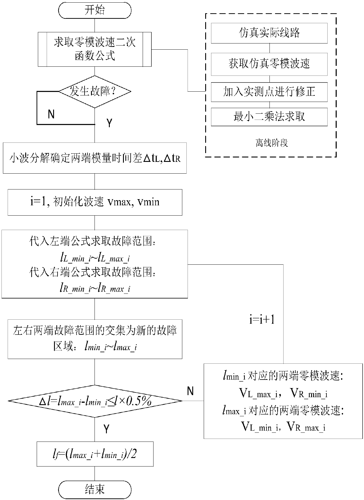
[0055] The transmission line iterative ranging method based on the zero-mode traveling wave velocity variation characteristics of the present invention, such as figure 1 As shown, the specific steps are as follows:

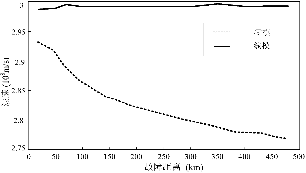
[0056] Step 1, for a determined transmission line with a total length of l, the quadratic function relationship formula v of the zero-mode traveling wave velocity with the fault distance is obtained by fitting the least square method 0 =f(x), where, v 0 Indicates the zero-mode traveling wave velocity, and x indicates the fault distance; specifically:

[0057] The length of the line is l, and N zero-mode wave velocities (an integer of N≥3) are collected along the line, and N zero-mode wave velocity sampling points are evenly distributed on the line. Taking the head end of the line as the reference point, the distance between each zero-mode traveling wave...


PUM


Abstract

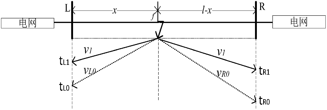
The invention discloses a transmission line iterative distance measuring method based on a zero-mode traveling wave velocity variation characteristic, belonging to a method of grid line fault positioning. After a fault occurs on a transmission line, a transient traveling wave is propagated on the line. According to the method, starting from propagation characteristics of the traveling wave on theline, the relationship between a traveling wave propagation distance and a traveling wave velocity is analyzed, and a function formula between a zero mode and a fault distance is obtained through least square fitting. Combined with a wave speed-distance formula and a time difference of a zero mode and a line mode at two ends of the line, with maximum and minimum zero mode wave velocity on the lineas an initial condition, a modulus time difference formula is substituted, and a precise fault point is positioned through iteration. According to the method, the synchronization of two ends of the line is not needed, the method is not influenced by factors of a system load and fault resistance, traveling wave measuring devices in substations at two ends of the line are used, and the realizationis convenient. The positioning precision is high, and the speed is fast. The positioning method of the invention can be used in trans-regional remote distance high-voltage power transmission line.

Description

technical field [0001] The invention belongs to the field of transmission line monitoring and protection, in particular to an iterative transmission line fault distance measurement method based on zero-mode traveling wave velocity variation characteristics. Background technique [0002] Due to the unbalanced distribution of my country's main energy bases and power loads, the distance of power transmission is long and the span is long, and the terrain and environment passed by the transmission lines are varied, and they are easily affected by factors such as natural environment and external force damage, resulting in short circuits, Faults such as grounding. The reliability of large-capacity transmission lines affects the economy and life of a region or even a larger region, and plays a vital role. Therefore, finding fault points is of great significance for timely repair of faulty lines. [0003] Currently, fault location methods for transmission lines are mainly divided int...

Claims


Application Information

Patent Timeline
IPC IPC(8): G01R31/08
Inventor 梁睿程孟晗刘成磊彭楠迟鹏王政
Owner CHINA UNIV OF MINING & TECH
Learn More