Dynamic smoke treatment equipment

A technology for processing equipment and dust, which is applied in the direction of particle charging/ionization, electrode structure, electrostatic separation, etc., can solve the problems of not achieving purification effect, gas blockage, environmental damage, etc., and achieve small pressure loss, simplified structure, and wide application The effect of using range

Pending Publication Date: 2018-01-26
漳州万力机械有限公司
View PDF0 Cites 0 Cited by
  • Summary
  • Abstract
  • Description
  • Claims
  • Application Information

AI Technical Summary

Problems solved by technology

[0002] Although my country's economy and technology have developed rapidly in recent years, our country's environment has been seriously damaged, and the country has begun to increase environmental governance. Therefore, dust removal equipment is often used in the process of industrial production. The so-called dust removal equipment refers to the equipment that separates dust from the flue gas, also called dust collector or dust removal equipment. Nowadays, ordinary purification devices generally use filter paper to filter the dust in the smoke, but it is very easy to cause filter paper to filter dust by using filter paper. If the pores are clogged, the dust will accumulate more and more, which will not only fail to achieve the effect of purification, but also easily cause gas clogging. Therefore, this kind of dust removal equipment can no longer meet the requirements of people's processing and production.

Method used


Image

  • Dynamic smoke treatment equipment
  • Dynamic smoke treatment equipment
  • Dynamic smoke treatment equipment

Examples


Embodiment 1

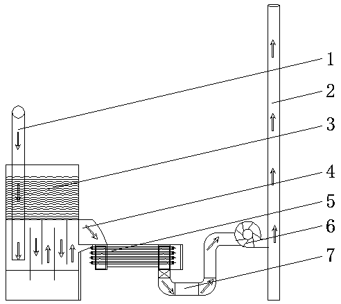
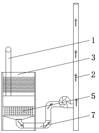
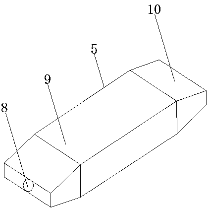
[0017] Such as Figure 1-4 Shown: dynamic soot treatment equipment, including steam outlet pipe 1, chimney 2, boiler 3, duct 4, dynamic soot adsorber 5, fan 6, U-shaped pipe 7, smoke inlet 8, shell 9, plug 10, The ion electrostatic tube 11 and the conductor 12, the upper end of the boiler 3 is provided with a steam outlet pipe 1, and the gas outlet on the side of the boiler 3 is sealed and connected with the smoke inlet 8 at one end of the smoke absorber 5 through the conduit 4, and the shell of the smoke absorber 5 There is an ion electrostatic tube 11 inside the body 9, which makes the ion electrostatic tube 11 have the adsorption capacity, so as to achieve the effect of purifying smoke and dust. Compared with other filter devices, this structure has a more efficient dust removal efficiency and will not cause gas blockage , can purify a large amount of air, save electric energy, and can remove particles with a wide range of particle sizes, and has a wide range of application...


PUM


Abstract

The invention discloses dynamic smoke treatment equipment. The dynamic smoke treatment equipment comprises a steam outlet pipe, a chimney, a boiler, a guide pipe, a dynamic smoke adsorber, a draught fan, a U-shaped pipe, a smoke inlet pipe, a shell, end caps, ionic electrostatic pipes and electric conductors. The upper end of the boiler is provided with a steam outlet pipe. The shell of the smokeadsorber is internally provided with the ionic electrostatic pipes, and the ionic electrostatic pipes are internally provided with the electric conductors. The two ends of the shell are both providedwith the end caps. The outer side faces of the end caps on the two sides of the shell are provided with the smoke inlet and a smoke outlet correspondingly. The smoke outlet of the smoke adsorber is insealed connection with one end of the U-shaped pipe, the other end of the U-shaped pipe is in sealed connection with an air inlet of the draught fan, and an air outlet of the draught fan is in sealedconnection with the chimney. According to the dynamic smoke treatment equipment, by means of the high-frequency and high-pressure technology, the ionic electrostatic pipes have adsorption capacity, and therefore the effect of purifying smoke is achieved; and compared with other filtering devices, by adopting the structure, the dynamic smoke treatment equipment achieves high-efficiency smoke removing efficiency, and gas blockage cannot be caused.

Description

technical field [0001] The invention relates to the technical field of dust removal equipment, in particular to a dynamic smoke and dust treatment equipment. Background technique [0002] Although my country's economy and technology have developed rapidly in recent years, our country's environment has been seriously damaged, and the country has begun to increase environmental governance. Therefore, dust removal equipment is often used in the process of industrial production. The so-called dust removal equipment refers to the equipment that separates dust from the flue gas, also called dust collector or dust removal equipment. Nowadays, ordinary purification devices generally use filter paper to filter the dust in the smoke, but it is very easy to cause filter paper to filter dust by using filter paper. If the pores are clogged, the dust will accumulate more and more, which will not only fail to achieve the effect of purification, but also easily cause gas clogging. Therefore, ...

Claims


Application Information

Patent Timeline
Patent Type & Authority Applications(China)
IPC IPC(8): B03C3/38B03C3/41B03C3/45B03C3/34
Inventor 蔡小强
Owner 漳州万力机械有限公司
Why Eureka
Try Eureka