Thermal power generating unit deep peak regulation and backheating energy saving method

A technology for thermal power units and cogeneration units, which is applied in the directions of chemical instruments and methods, separation methods, lighting and heating equipment, etc., can solve problems such as increasing power generation load, reduce coal consumption, save operating energy consumption, and reduce the amount of heating steam Effect

Inactive Publication Date: 2018-01-26
北京姚魏环保技术有限公司
View PDF5 Cites 10 Cited by
  • Summary
  • Abstract
  • Description
  • Claims
  • Application Information

AI Technical Summary

Problems solved by technology

[0013] In order to solve the problem of deep peak regulation in the power system in the prior art, the present invention proposes a method for deep peak regulation of thermal powe

Method used


Image

  • Thermal power generating unit deep peak regulation and backheating energy saving method
  • Thermal power generating unit deep peak regulation and backheating energy saving method

Examples


no. 1 example

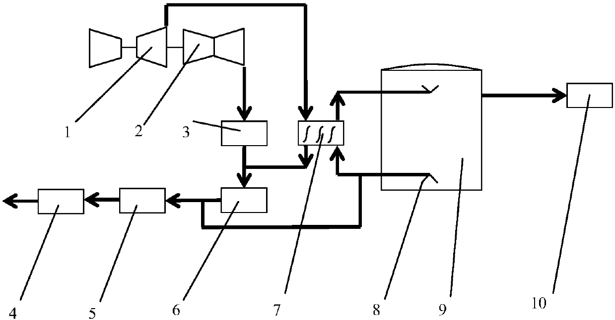
[0035] The deep peak regulation and heat recovery energy-saving method of the thermal power unit in this embodiment is based on the following figure 1 system shown. The thermal power unit of this embodiment is described by taking the thermal power unit system transformed by the micro-oil ignition and stable combustion system as an example. Such as figure 1 As shown, the thermal power unit system includes: medium pressure cylinder 1; low pressure cylinder 2; condenser 3; deaerator 4; low pressure heater 5; finishing processor 6; steam water heat exchanger 7; water distributor 8; Hot water storage tank 9; primary pipe network 10.

[0036] Wherein, the medium-pressure cylinder 1 is connected with one side of the low-pressure cylinder 2 and one side of the steam-water heat exchanger 7 at the same time, and the other side of the low-pressure cylinder 2 is connected with one side of the condenser 3; One side is connected with the other side of the steam-water heat exchanger 7 and...

no. 2 example

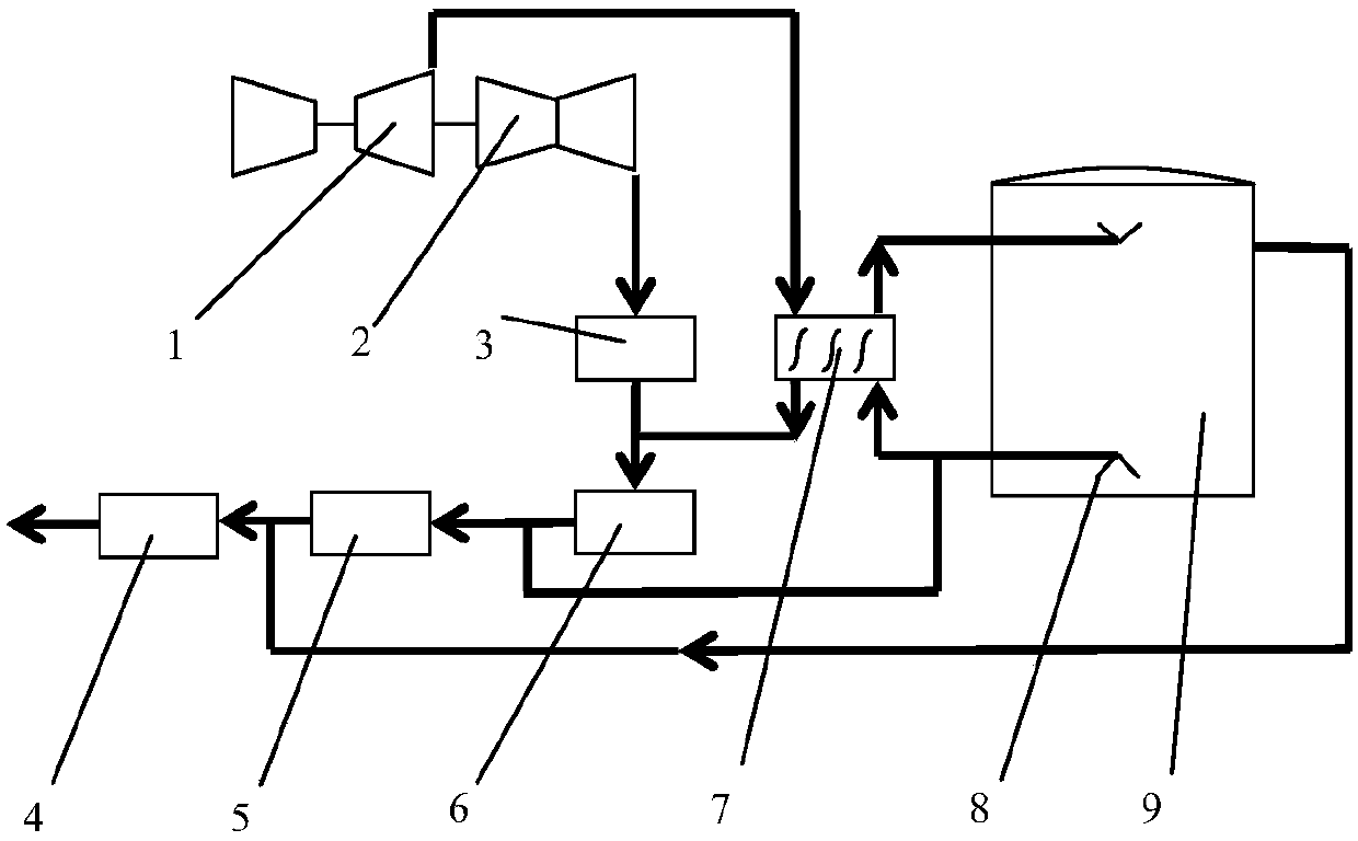
[0045] The deep peak regulation and heat recovery energy-saving method of the thermal power unit in this embodiment is based on the following figure 2 system shown. Such as figure 2 As shown, the thermal power unit system includes: medium pressure cylinder 1; low pressure cylinder 2; condenser 3; deaerator 4; low pressure heater 5; finishing processor 6; steam water heat exchanger 7; water distributor 8; Hot water storage tank 9.

[0046] The method for deep peak regulation and heat recovery energy saving of thermal power units in this embodiment is basically the same as that of the first embodiment, the difference is that the method for deep peak regulation of thermal power units in this embodiment is based on figure 2 system shown. figure 2 The system shown with figure 1 The difference of the shown system is that the hot water in the upper part of the hot water storage tank 9 in the first embodiment is supplied to the primary pipe network, while the hot water storage...


PUM


Abstract

The invention provides a thermal power generating unit deep peak regulation and backheating energy saving method. Through a manner that a hot water heat storing system is arranged in a thermal power generating unit system, at the period when deep peak regulation needs to be participated in, exhaust steam in a pressure cylinder in the unit is extracted, cold water is heated through a heat exchanger, heated water is stored in a heat storage water tank, and deep peak regulation is achieved; meanwhile, the power generation load is reduced, and continuous and stable running of the unit is guaranteed; and at the period when deep peak regulation does not need to be participated in, hot water in the heat storage water tank is supplied to a condensed water pipe in front of a deaerator through a water pump, and therefore heat stored at the deep peak regulation period is sufficiently used, the heating steam amount of a low-pressure heater system at present is greatly reduced, and the aims of increasing the power generation load, recycling the heat stored in the heat storage water tank and reducing the coal consumption are achieved. In the overall peak regulation process, the hot water heat storage technology is applied, the on-grid peak regulation capacity of the unit is improved, the running energy consumption of the unit is saved, and the dilemma of clean energy consumption is effectively released.

Description

technical field [0001] The invention belongs to the field of electric energy, and in particular relates to a method for deep peak regulation and heat recovery and energy saving of a thermal power unit. Background technique [0002] In recent years, the increase in energy demand and the depletion of non-renewable resources have led to the rapid development of technologies related to renewable resources. In terms of electricity, wind power has achieved sustained and rapid development, but there are also common technical difficulties, such as serious wind curtailment. One of the main factors leading to the problem of wind curtailment is the limitation of wind power absorption capacity. Consumption has become a key factor restricting the development of domestic wind power and the situation is becoming increasingly severe. To solve the problem of wind power consumption, measures can be taken from various aspects such as improving power peak shaving capability, adjusting wind po...

Claims


Application Information

Patent Timeline
IPC IPC(8): F22D1/34F22D1/50F22D3/00
Inventor 单涛赵涛孔德伦武广超
Owner 北京姚魏环保技术有限公司
Why Eureka
Try Eureka