Geostationary satellite imaging navigation and registered orbital motion compensation method

A technology for orbiting and stationary satellites, applied in the field of orbital motion compensation

Inactive Publication Date: 2018-01-26
SHANGHAI SATELLITE ENG INST
View PDF3 Cites 14 Cited by
  • Summary
  • Abstract
  • Description
  • Claims
  • Application Information

AI Technical Summary

Problems solved by technology

There is no special compensation method designed specifically for the impact of orbital drift

Method used


Image

  • Geostationary satellite imaging navigation and registered orbital motion compensation method
  • Geostationary satellite imaging navigation and registered orbital motion compensation method
  • Geostationary satellite imaging navigation and registered orbital motion compensation method

Examples


Embodiment

[0023] This embodiment relates to an orbital motion compensation method for imaging navigation and registration of a stationary satellite.

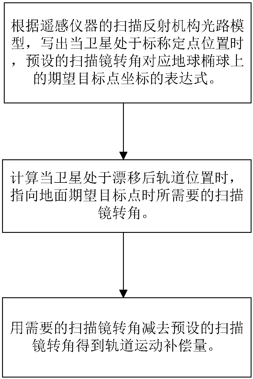
[0024] 1. The coordinate calculation of the desired target point on the ground

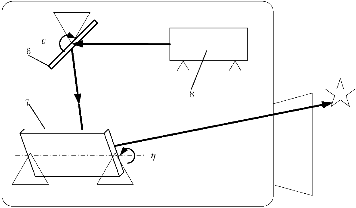
[0025] According to the optical path characteristics of the satellite imager, without considering the thermal deformation of the instrument and the satellite attitude deviation, when the rotation angle of the east-west mirror 6 is ε and the rotation angle of the north-south mirror 7 is η, the unit vector of the line-of-sight of the satellite imager 8 is in the ground-solid system. The components are as follows (1):

[0026]

[0027] Among them, LS 0 Is the unit vector of the outgoing line of sight, A fr It is the coordinate conversion matrix from the satellite attitude reference coordinate system to the ground-fixed system, which is a function of the current time and the geographic longitude of the fixed point of the geostationary satellite. Px, Py, and Pz respectiv...


PUM


Abstract

The invention provides a geostationary satellite imaging navigation and registered orbital motion compensation method. The method includes the following steps: a first step, writing an expression of adesired target point coordinate on an earth ellipsoid corresponding to a preset scanning mirror rotation angle according to a scanning reflective mechanical optical path model of a remote sensing instrument while a satellite is at a nominal fixed point; a second step, calculating a desired scanning mirror rotation angle while the satellite is at an orbital position after drifting and points to aground desired target point; and a third step, using the desired scanning mirror rotation angle to subtract the preset scanning mirror rotation angle to acquire an orbital motion compensation amount.The acquired image and an earth nominal grid image generated by the satellite at the nominal fixed point are consistent, errors are controlled in an indication range, and the research and developmentdifficulty of a system can be lowered, and the realizability of engineering can be improved.

Description

Technical field [0001] The invention relates to an orbital motion compensation method, in particular to an orbital motion compensation method for imaging navigation and registration of a stationary satellite. Background technique [0002] In numerical weather forecasting, it is necessary to locate regional complex weather, track the development trend of severe weather, and generate cloud image animation. This requires accurate positioning of the absolute geographic location corresponding to the image and accurate registration of the relative position relationship between adjacent images. The accuracy of imaging navigation registration is related to the accuracy of weather diagnosis, cloud image analysis, target recognition for disaster monitoring applications, and the processing accuracy of quantitative remote sensing products such as wind vectors. However, satellite platforms and remote sensing instruments are affected by factors such as the space mechanical environment and the...

Claims


Application Information

Patent Timeline
Patent Type & Authority Applications(China)
IPC IPC(8): G06F17/50
Inventor 吕旺信思博王田野王皓沈毅力张海
Owner SHANGHAI SATELLITE ENG INST
Why Eureka
Try Eureka