Medical orthopedic implantation bundling strap

A strapping and orthopedic technology, which is applied in the field of medical orthopedic implant strapping, can solve the problems of difficult shaping, split sternum, and open sternum, and achieve the effect of not easy to loosen or fall off, not easy to slip, and tightly meshed

Pending Publication Date: 2018-01-30
苏州爱宝利恩精密器械科技有限公司
View PDF6 Cites 3 Cited by
  • Summary
  • Abstract
  • Description
  • Claims
  • Application Information

AI Technical Summary

Problems solved by technology

[0003] However, there are many insurmountable shortcomings in this traditional method, such as: poor stability of sternal drilling, complicated operation, and secondary injury to patients, especially for elderly patients with osteoporosis and infants with thin bones. For young children, if the steel wire is tied too tightly, it will easily cause sternum splitting, and if it is too loose, the sternum will open; causing mediastinal infection
In addition, due to the poor compatibility between metal and human tissue, it is not conducive to postoperative recovery, and because of human rejection, even after recovery, patients still have a lot of discomfort.
[0004] At present, the industry has developed a binding strap locking device that can be used for orthopedic implants. However, since the straps used for orthopedic implants need to be firmly tied at the pathological site for a long time, it is necessary to avoid negative effects on patients due to the fracture of the straps. Affect, or even require multiple operations to replace or refix the strap, aggravate the patient's pain and increase medical expenses, so the strap for orthopedic implants generally adopts a melting point above 300 ° C, a softening point above 150 ° C, and stretching Made of high-strength special polymer material
However, the strapping straps for orthopedic implants in the prior art are also affected by their own materials. Because the molding is not easy, they generally adopt a relatively simple structure. Part reliability

Method used


Image

  • Medical orthopedic implantation bundling strap
  • Medical orthopedic implantation bundling strap
  • Medical orthopedic implantation bundling strap

Examples


Embodiment

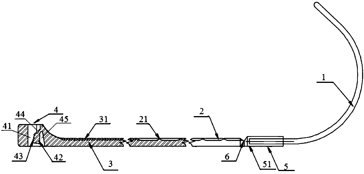
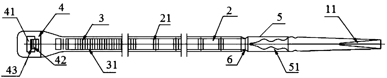
[0039] Such as Figure 1 to Figure 7 As shown, the medical orthopedic implant strap of this embodiment also includes an injection molding coating section 5, the injection molding coating section 5 includes an injection molding coating layer 51, and one end of the injection molding coating layer 51 is connected to the piercing section 2, and the piercing section 1 faces the piercing section 2. One end of the leading section 2 is covered in the injection molding coating layer 51 .

[0040]A cutting groove 6 is provided between the injection molding coating section 5 and the threading section 2 . It can be used to mark the cut-off position of the metal puncture segment, which is convenient for cutting off the puncture head at a suitable position after the puncture is completed, avoiding the damage of the puncture head to human tissues during further operations, and improving the efficiency of the operation.

[0041] refer to figure 1 The reed 42 includes a reed body and an L-sh...


PUM


Abstract

The invention discloses a medical orthopedic implantation bundling strap which comprises a puncture section, a threading section, a lock tooth section, a locking ring and a lock plate which are sequentially arranged. The threading section, the lock tooth section and the locking ring are integrally formed, a puncture head is arranged at one end of the puncture section, and the other end of the puncture section is fixedly connected with the threading section; a plurality of lock teeth are continuously arranged on a bone clinging surface of the lock tooth section; the locking ring comprises a lock hole, the threading section and the lock tooth section can penetrate the lock hole, a side of the periphery of the lock hole is connected with the lock tooth section, and the two end surfaces of thelocking ring are connected with the bone clinging surface and the other surface of the lock tooth section; an armature spring is arranged in the lock hole, one end of the armature spring is connectedwith a side wall of the lock hole, the other end of the armature spring is a free end, and accordingly a variable gap is reserved between the armature spring and the connected side wall of the lock hole; more than one armature spring lock tooth which can mesh with the lock teeth on the lock tooth section is arranged on the side, which is far away from the variable gap, of the armature spring; theshape of the lock plate is adaptive to the shape of the variable gap when the lock teeth on the lock tooth section mesh with the armature spring lock teeth, so that the lock plate can be inserted inthe variable gap in an interference fit manner.

Description

technical field [0001] The invention relates to the technical field of medical auxiliary equipment, in particular to a medical orthopedic implant strap. Background technique [0002] Generally, when performing thoracotomy for patients in domestic and foreign medical industries, it is necessary to split the sternum along the median path of the chest (that is, saw the sternum along the longitudinal direction). Drill holes on the sternum on both sides, use medical stainless steel or other alloy steel wires to penetrate into the holes and bind them firmly, and finally suture the muscle tissue and skin. [0003] However, there are many insurmountable shortcomings in this traditional method, such as: poor stability of sternal drilling, complicated operation, and secondary injury to patients, especially for elderly patients with osteoporosis and infants with thin bones. For young children, if the steel wire is too tight, it will easily cause sternal rupture, and if it is too loose...

Claims


Application Information

Patent Timeline
Patent Type & Authority Applications(China)
IPC IPC(8): A61B17/82A61B17/84
Inventor 刘永江朱双珠刘勇金毅
Owner 苏州爱宝利恩精密器械科技有限公司
Why Eureka
Try Eureka