Dislocation-resistant hip joint prosthesis of 3D printing femoral head and manufacturing method thereof

A hip joint prosthesis and printing stock technology, applied in the medical field, can solve the problems of hip joint dislocation, damage to the locking mechanism, limited over-radius range of the acetabular lining, etc., and achieve the effect of increasing restraint and preventing dislocation

Pending Publication Date: 2018-01-30
北京大学国际医院
View PDF13 Cites 2 Cited by
  • Summary
  • Abstract
  • Description
  • Claims
  • Application Information

AI Technical Summary

Problems solved by technology

First of all, increasing the diameter of the femoral head will inevitably reduce the thickness of the acetabular lining, thereby affecting the life of the acetabular lining
Furthermore, previous studies have found that increasing the diameter of the femoral head will increase the wear between the acetabular lining and the femoral head, thereby affecting the life of the prosthesis
2. Increase the local high side of the acetabular lining to form a super radius of the acetabular lining, which can increase the tolerance of the acetabular lining to the femoral head. However, the acetabular lining and the femoral head are currently manufactured se

Method used


Image

  • Dislocation-resistant hip joint prosthesis of 3D printing femoral head and manufacturing method thereof
  • Dislocation-resistant hip joint prosthesis of 3D printing femoral head and manufacturing method thereof
  • Dislocation-resistant hip joint prosthesis of 3D printing femoral head and manufacturing method thereof

Examples


Embodiment 1

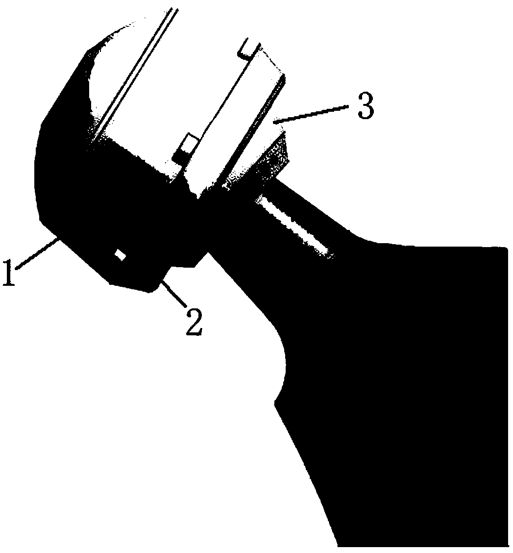
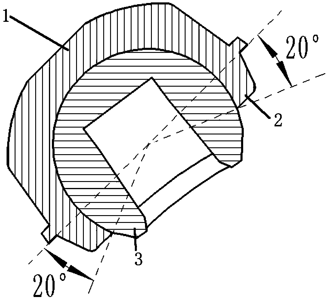
[0029] like figure 1 and figure 2 The hip joint prosthesis shown includes the acetabular lining, the acetabular lining is provided with a hemispherical groove 1, the edge of the hemispherical groove 1 is integrally formed with a super-radius buckle edge 2, and the inside of the acetabular lining There is a 3D printed femoral head prosthesis 3, the 3D printed femoral head prosthesis 3 is spherical, the 3D printed femoral head prosthesis 3 is the same size as the internal space of the acetabular lining, and the diameter of the opening of the super-radius buckle is smaller than 3D Print the diameter of the femoral head prosthesis 3, and the 3D printed femoral head prosthesis 3 is provided with a femoral neck prosthesis (the square groove in the middle of the femoral head on the way of the section is the position where the femoral neck is installed). The acetabular lining is made of highly cross-linked polyethylene, and the femoral head prosthesis is 3D printed with metal materi...

Embodiment 2

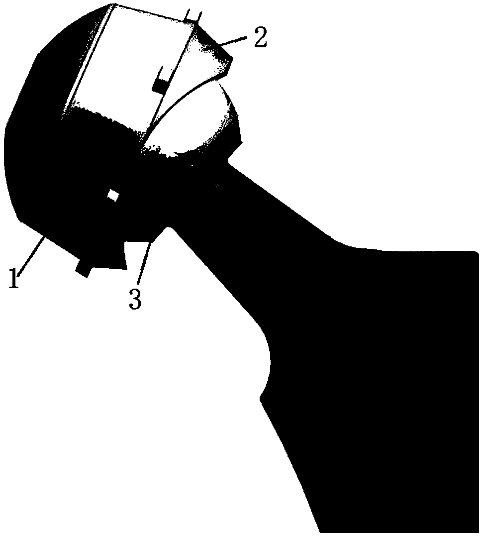
[0036] like image 3 and Figure 4 As shown, in this embodiment, the super-radius button edge on the acetabular lining is designed in a wavy shape, including two high points and two low points, and the distance between two adjacent points is a quarter of a circle and the distance between two adjacent points is wavy. There is a smooth curve connection between them; the super-radius buckle does not exceed the radius at the first low point and the second low point, and the super-radius buckle at the first high point has an arc of 10°-40°, and the super-radius buckle The super-radius arc at the second highest point is 5°-25°. And the sum of the super-radius radians at the first high point and the second high point should be less than 45°. It is equivalent to extending two wavy super-radius buckle edges integrally from the upper and lower parts of the hemispherical groove, and forming two left and right grooves at the intersection of the two waves ( image 3 The upper wave-shaped ...


PUM


Abstract

Dislocation-resistant hip joint prosthesis of a 3D printing femoral head comprises an acetabulum lining. The dislocation-resistant hip joint prosthesis is characterized in that a hemispherical grooveis formed in the acetabulum lining, the edge of the hemispherical groove integrally extends to form an ultra-diameter buckling edge, 3D printing femoral head prosthesis is arranged inside the acetabulum lining, is spherical and is uniform to size of inside space of the acetabulum lining, diameter of an opening of the ultra-diameter buckling edge is smaller than that of the 3D printing femoral headprosthesis, and femoral neck prosthesis is arranged on the 3D printing femoral head prosthesis.

Description

technical field [0001] The invention relates to the medical field, in particular to a 3D printed femoral head anti-dislocation hip joint prosthesis and a manufacturing method thereof. Background technique [0002] Artificial total hip replacement has been used as a routine operation for the treatment of severe hip osteoarthritis, advanced femoral head necrosis and femoral neck fracture in the elderly, and its curative effect has been clinically confirmed. Osteoarthritis disease, until now young patients have recovered good function of the hip joint through hip replacement surgery. The progress of bioengineering and material science undoubtedly plays a pivotal role, but there are also some complications after hip replacement surgery, such as aseptic Sexual loosening, periprosthetic infection and dislocation after hip replacement. Previous studies have reported that the incidence of prosthetic dislocation after hip replacement is 1% to 3%, second only to aseptic loosening, an...

Claims


Application Information

Patent Timeline
IPC IPC(8): A61F2/34A61F2/36
Inventor 刘晨张克辛星刘新光王军峰
Owner 北京大学国际医院
Why Eureka
Try Eureka