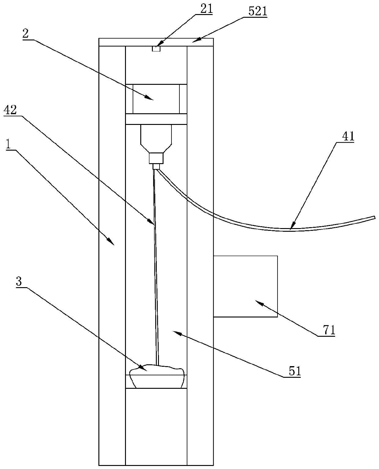
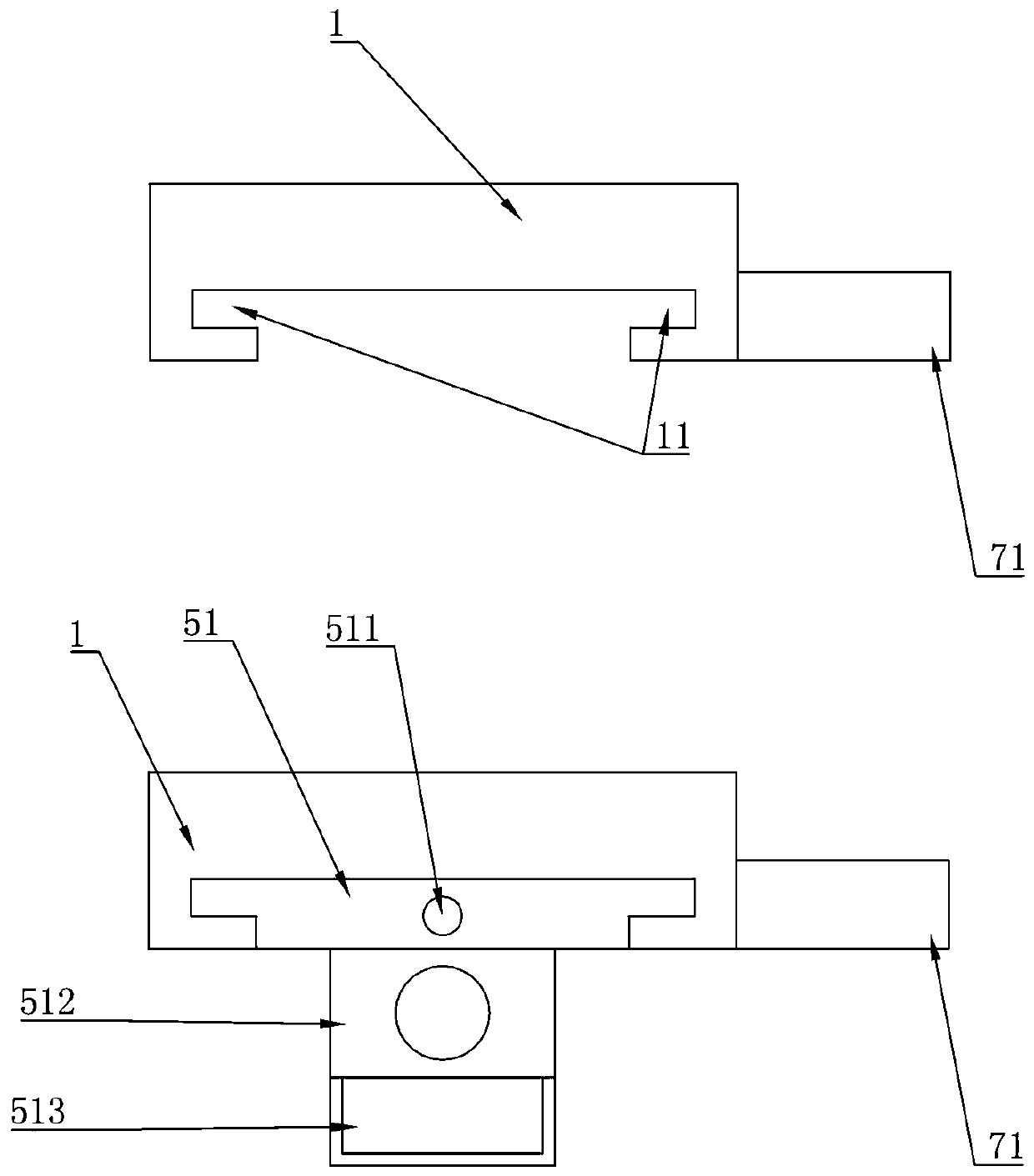
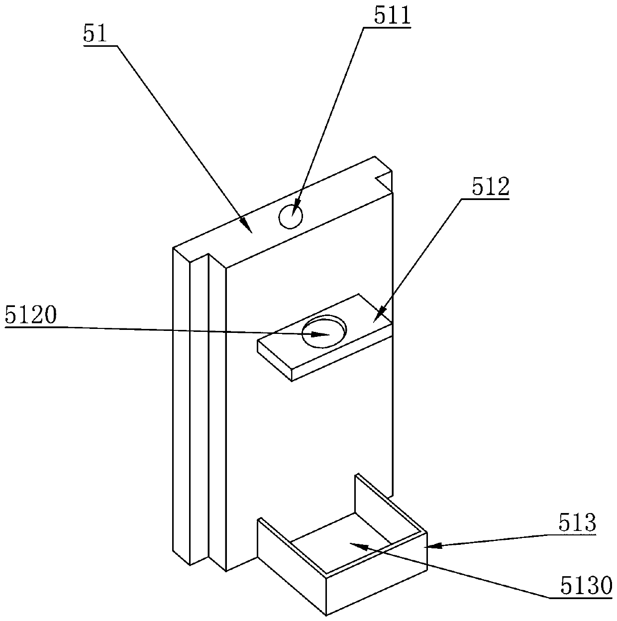
Pressure monitoring and adjusting device for external drainage system

A technology of pressure monitoring and extracorporeal drainage, which is applied in the field of surgery, can solve the problems of repeated adjustment, troublesome operation, and influence on the treatment effect, so as to improve the recovery speed and probability of recovery, increase the accuracy of the up and down height, and improve the treatment effect.

Pending Publication Date: 2018-01-30
WENZHOU CENT HOSPITAL
View PDF2 Cites 6 Cited by
  • Summary
  • Abstract
  • Description
  • Claims
  • Application Information

AI Technical Summary

Problems solved by technology

At present, when major hospitals perform drainage operations, most of them fix the intracranial pressure regulating bottle on the appropriate position of the bed frame or infusion stand, and adjust the height of the intracranial pressure regulating bottle at any time according to the drainage process and the development of the disease to control the drainage speed. When adjusting, the intracranial pressure adjustment bottle is not easy to fix or the height span is large, which is troublesome to operate and affects the drainage effect; the adjusted height is determined entirely by the experience of medical staff, and the error is large, which not only affects the treatment effect, but also easily causes other diseases
Even if some hospitals have a scale plate on the bed frame or infusion stand, the intracranial pressure regulating bottle is fixed on the scale plate, and the patient’s current intracranial pressure is read according to the height position of the scale plate, and the intracranial pressure regula

Method used


Image

  • Pressure monitoring and adjusting device for external drainage system
  • Pressure monitoring and adjusting device for external drainage system
  • Pressure monitoring and adjusting device for external drainage system

Examples


specific Embodiment approach

[0028] As an improved specific embodiment, the detection device 92 includes: a miniature pressure sensor 411 and a wire 412. The miniature pressure sensor 411 is fixedly connected to one end of the catheter 41 penetrating into the lateral ventricle, and is used to detect cerebral hydraulic pressure. For force data, one end of the wire 412 is coupled to the miniature pressure sensor 411 and the other end is coupled to the controller 91 for transmitting the cerebrospinal fluid pressure data to the controller 91 . please see Figure 8 , in the process of using the present invention, the miniature pressure sensor is a miniature optical fiber Fabry pressure sensor, and the miniature pressure sensor 411 is installed on the side wall of one end of the catheter 41 inserted into the lateral ventricle, and penetrates into the lateral ventricle to detect the brain in the cranium Hydraulic pressure data, and send the cerebrospinal fluid pressure data to the controller 91 through the wire ...


PUM


Abstract

The invention discloses a pressure monitoring and adjusting device for an external drainage system. The pressure monitoring and adjusting device has the advantages that intracranial pressure data of apatient are detected by a detection device and transmitted to a controller, the controller transmits the intracranial pressure data to a display screen for display, so that a doctor can acquire the current intracranial pressure of a patient in real time, and determination of a therapeutic schedule of medical staff and therapy are accelerated. Besides, the acquired intracranial pressure of the patient is compared with intracranial pressure and intracranial pressure adjusting bottle relative adjustment height data in a database by the controller, an intracranial pressure adjusting bottle is adjusted to a corresponding height, a lifting device is driven by a lead screw, the lifting process is stable, and intracranial infection of the patient caused by lifting instability of the intracranialpressure adjusting bottle is avoided. When the intracranial pressure adjusting bottle rises to be abutted to a lead screw fixing plate, the abutting detection device generates abutting signals and transmits the abutting signals to the controller, the controller outputs alarm signals and the intracranial pressure data to an external hospital duty room, and an operator on duty timely finds and handles the abnormal condition of the patient.

Description

technical field [0001] The invention relates to the field of surgery, and more specifically relates to a pressure monitoring and adjusting device for an external drainage system. Background technique [0002] Extracranial and lumbar puncture tube placement for continuous external drainage is a common treatment measure in clinical neurosurgery. Draining cerebrospinal fluid can relieve the increase in intracranial pressure and accelerate the discharge of inflammatory or bloody cerebrospinal fluid. [0003] The extracorporeal drainage system includes a drainage catheter, a cranial pressure regulating bottle, and an effusion bag; we know that adjusting the position of the cranial pressure regulating bottle can control the drainage speed. At present, when major hospitals perform drainage operations, most of them fix the intracranial pressure regulating bottle on the appropriate position of the bed frame or infusion stand, and adjust the height of the intracranial pressure regulat...

Claims


Application Information

Patent Timeline
IPC IPC(8): A61M1/00A61B5/03
Inventor 蔡建勇孙军陆川林群巴华君陈献东戴君侠陈茂华李志伟
Owner WENZHOU CENT HOSPITAL
Why Eureka
Try Eureka