Contraposition linear reciprocating pump driving mechanism

A driving mechanism, linear reciprocating technology, applied in the field of reciprocating pumps, can solve the problems of increased wearing parts, shortened service life, increased friction between the crosshead and the rack slide, etc., achieves small vibration and noise, and shortened service life. , Eliminate the effect of poor lubrication

Pending Publication Date: 2018-01-30
宝鸡航天动力泵业有限公司
View PDF0 Cites 4 Cited by
  • Summary
  • Abstract
  • Description
  • Claims
  • Application Information

AI Technical Summary

Problems solved by technology

[0003] 1. Partial rotation of the connecting rod bushing and crosshead pin may cause poor lubrication and uneven wear, making it the most prone to failure at the power end of the reciprocating pump. When used as a hydraulically balanced booster pump, the suction Pressure changes are more likely to cause poor lubrication or even burnt connecting rod small end bushings and crosshead pins, seriously affecting their service life
[0004] 2. Since the connecting rod swings within the angle range of α, a force (lateral force) acting vertically on the rack slideway and the outer circle of the crosshead will be generated through the crosshead pin to increase the crosshead and crosshead outer circle. The friction of the slideway of the rack will cause its wear to be accelerated and its service life to be shortened. At the same time, it will also cause partial wear of the plunger, which will shorten the service life of the plunger and seal
[0005] 3. Because the connecting rod has two kinds of motions: rotation around the crankshaft and swing within the range of α, the acceleration during the crosshead movement is constantly changing, resulting in uneven flow of the reciprocating pump, resulting in flow pulsation and pressure pulsation. This kind of pulsation is very detrimental to the normal operation of the pump set and the safe operation of the pipeline system
[0006] 4. When the traditional reciprocating pump is made into an opposed structure, the big head of the connecting rod has a complicated structure, and two different connecting rod and bearing bush structures are required, which makes the structure of the pump set complex, the number of wearing parts increases, and the volume is large

Method used


Image

  • Contraposition linear reciprocating pump driving mechanism
  • Contraposition linear reciprocating pump driving mechanism
  • Contraposition linear reciprocating pump driving mechanism

Examples


Embodiment Construction

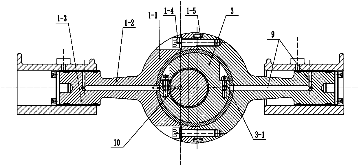
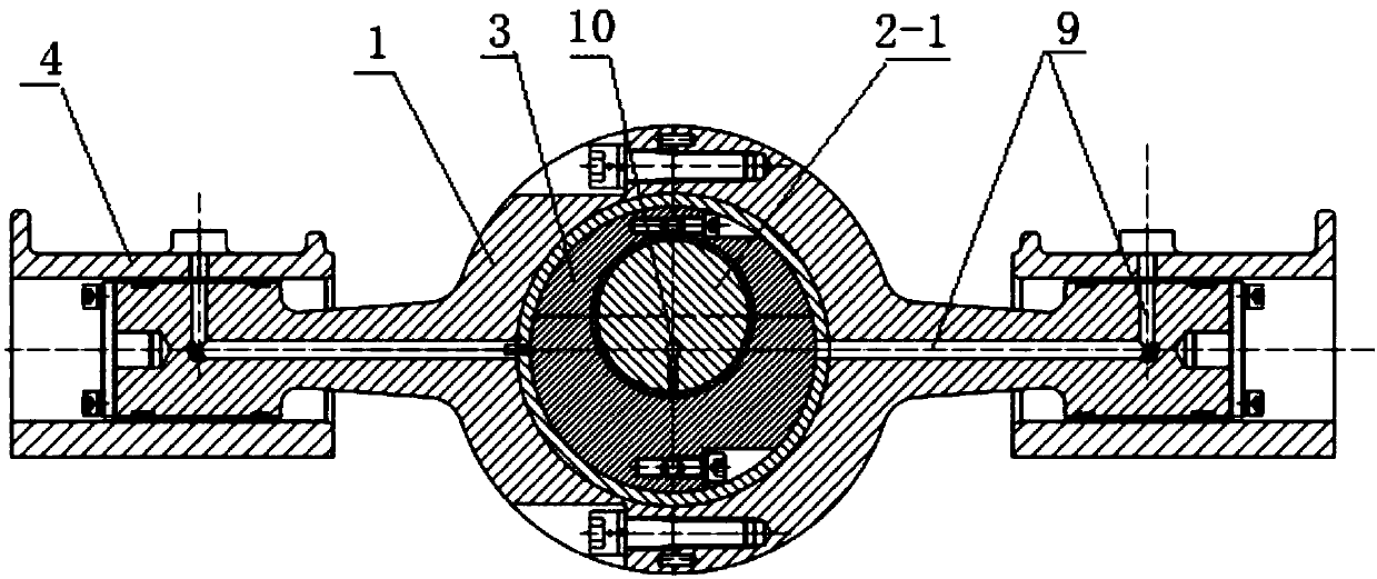
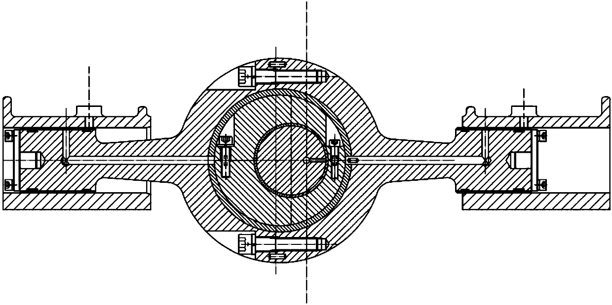
[0023] Attached below figure 1 , 2 , 3, 4, 5, 6 and specific embodiments describe the present invention in detail.

[0024] An opposed linear reciprocating pump drive mechanism, including a slider mechanism 1, a crankshaft 2, and an eccentric slider 3. The slider mechanism 1 is formed from a slider 1-1 in the middle and extends from both ends of the slider 1-1. The two connecting rods 1-2 and the pistons 1-3 at the ends of the two connecting rods 1-2 are composed, and the central axis of the two pistons 1-3 is perpendicular to the central axis of the slider 1-1; The crankshaft 2-1 of the crankshaft 2 is fitted with an eccentric slider 3, the slider 1-1 is concentrically set on the eccentric slider 3, and the piston 1-3 is coaxially inserted into the frame of the reciprocating pump. In the two symmetrical slideways 4; the eccentric slider 3 rotates around the crankshaft 2-1 while following the crankshaft 2-1 around the crankshaft 2, and the rotation direction of the eccentric...


PUM


Abstract

The invention discloses a contraposition linear reciprocating pump driving mechanism. The contraposition linear reciprocating pump driving mechanism comprises a slide block mechanism, a crankshaft andan eccentric slide block, wherein the slide block mechanism is composed of a slide block, two connection rods and two pistons, and the central axis of the two pistons is orthogonal to that of the slide block; a crank throw of the crankshaft is sleeved with the eccentric slide block, the slide block concentrically sleeves the eccentric slide block, and the pistons are coaxially inserted into two symmetric slide ways on a reciprocating pump rack; the eccentric slide block rotates on the axis of the slide block around the crank throw while following the crank throw to rotate around the crankshaft, in the entire rotation process, the center axis of the eccentric slide block is maintained parallel to the center axis of the crank throw all the time, so that the movement trail of the eccentric slide block in the horizontal direction is approximately linear, through the eccentric slide block, the slide block is driven to conduct linear movement, and then the two pistons conduct reciprocatinglinear movement in the two symmetric slide ways of the reciprocating pump respectively.

Description

technical field [0001] The invention belongs to the technical field of reciprocating pumps, and in particular relates to an opposed linear reciprocating pump driving mechanism. Background technique [0002] In addition to direct acting pumps (such as steam reciprocating pumps, hydraulically driven linear reciprocating pumps), traditional reciprocating pumps are mainly reciprocating pumps with crank (crank) linkage mechanism. The crosshead pin and the crosshead convert the rotary motion of the prime mover (motor, diesel engine, etc.) The movement of the cavity will cause the volume and pressure of the closed cavity at the liquid end of the reciprocating pump to change, so that the liquid medium can be transported through the suction and discharge valves. The traditional crank (crank throw) connecting rod mechanism reciprocating pump, because the connecting rod swings within the angle range of α with the crosshead pin as the center when the crankshaft rotates, it will cause m...

Claims


Application Information

Patent Timeline
Patent Type & Authority Applications(China)
IPC IPC(8): F04B1/02F04B53/22F04B53/14F04B53/18F04B53/00
Inventor 王雨团李彦喜王别好汤文婕王超赵琳娜
Owner 宝鸡航天动力泵业有限公司
Why Eureka
Try Eureka