A Calibration Method of Double Grating Focal Length Measuring Instrument

A calibration method and double grating technology, applied in the direction of testing optical performance, etc., can solve the problems of limited accuracy, limited medium and long focal length measurement systems, lack of high-precision measurement methods for accurate measurement, etc., to improve calibration accuracy and reduce complexity. Effect

Active Publication Date: 2019-08-09
NANJING UNIV OF SCI & TECH
View PDF5 Cites 0 Cited by
  • Summary
  • Abstract
  • Description
  • Claims
  • Application Information

AI Technical Summary

Problems solved by technology

Traditional measurement methods include magnification method, precision angle measurement method, Fourier spectrum method, etc., which are convenient and high-precision when measuring optical components with small focal lengths, but it is difficult to meet the measurement of long focal lengths due to space limitations.
The Tabermore method measures the focal length, and the double-grating interferometer is the key component. The linear Ronchi grating needs to calibrate the angle between the grating lines before measuring the focal length. The calibration method is complicated and the accuracy is limited.
[0003] The existing method of calibrating the angle between grating lines needs to know the standard value of the focal length of the calibration lens. For optical elements with medium and long focal lengths above 5m, there is no effective high-precision measurement method to accurately measure the focal length value, which furthermore Severely limits the accuracy of calibration and calibration of medium and long focal length measurement systems using corresponding standard parts
In addition, the focal length measurement range of the system is relatively large. Because of the focal length error of the calibration lens itself and the existence of various measurement system errors, the existing method uses a standard lens with a specific focal length value to calibrate the system, and it is difficult to measure the entire focal length. Achieve high measurement accuracy within the measurement range

Method used


Image

  • A Calibration Method of Double Grating Focal Length Measuring Instrument
  • A Calibration Method of Double Grating Focal Length Measuring Instrument
  • A Calibration Method of Double Grating Focal Length Measuring Instrument

Examples


Embodiment

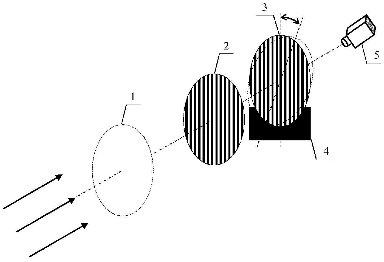
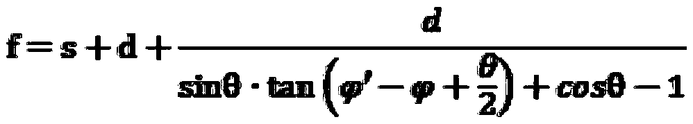
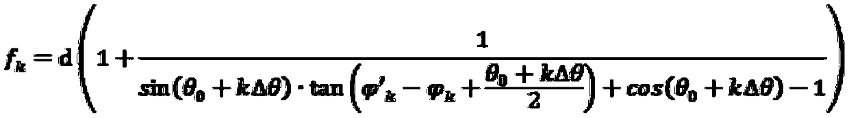
[0043] In this embodiment, calibration lenses with focal length design values ​​of 5m and 59m are used. By adjusting the high-precision precision angular displacement stage, the step length of the included angle of the grating line is adjusted with equal precision in each step, k=20, and the included angle of the grating line is changed to obtain the corresponding The interference fringes are collected by the imaging acquisition system and solved by Fourier transform through the interference fringe angle calculation software package. After each adjustment, return the precision angular displacement stage to zero before performing the next adjustment to ensure repeatable positioning accuracy. Bring all the data into the equation system, apply the focal length non-correlated least squares calibration method for combined calibration, and accurately solve the zero error Δθ of the double grating interferometer 0 Adjust the step size Δθ with the grid line angle.

[0044] Calibration...


PUM


Abstract

The invention discloses a calibration method of a double-grating focal length measuring instrument. A grating line included angle in the double-grating interferometer is calibrated through two lenseswith known focal length design values, and the focal length error of the two lenses with known focal length design values is eliminated, so that the double-grating grid line included angle calibrationprecision and the measuring precision of the focal length measuring instrument are guaranteed. An optimized focal length measuring formula is used, and the included angle between interference fringesand a zero reference line is replaced by the difference between the included angle between the two sets of interference fringes placed in front and behind a to-be-measured element. The problem that an interference fringe zero reference line is difficult to determine is solved, and the influence of an error on the focal length measurement is eliminated.

Description

technical field [0001] The invention belongs to the field of optical precision testing, and in particular relates to a calibration method of a double grating focal length measuring instrument. Background technique [0002] At present, there are mainly traditional measurement methods and the Tabermore method for measuring the focal length of long focal length optical systems. Traditional measurement methods include magnification method, precision angle measurement method, Fourier spectrum method, etc., which are convenient and high-precision when measuring optical components with small focal lengths, but it is difficult to meet the measurement of long focal lengths due to space limitations. The Tabermore method measures the focal length, and the double grating interferometer is the key component. Before measuring the focal length of the linear Ronchi grating, the angle between the grating lines of the grating needs to be calibrated. The calibration method is complicated and t...

Claims


Application Information

Patent Timeline
Patent Type & Authority Patents(China)
IPC IPC(8): G01M11/02
Inventor 李浩宇何佳竻何勇蒋正东刘尧李建欣朱日宏郑云瀚许逸轩朱荣刚朱庆生
Owner NANJING UNIV OF SCI & TECH
Why Eureka
Try Eureka