An automatic test method for the drag speed of electronic countermeasure equipment

An electronic countermeasures and automatic test technology, applied in the field of testing, can solve the problems of low test efficiency, large random error of drag speed, deviation from the true value, etc., to reduce the uncertainty of operation and observation, reduce the requirements of work skills, The effect of reducing work intensity

Inactive Publication Date: 2019-07-30
THE 41ST INST OF CHINA ELECTRONICS TECH GRP
View PDF3 Cites 0 Cited by
  • Summary
  • Abstract
  • Description
  • Claims
  • Application Information

AI Technical Summary

Problems solved by technology

[0009] 1) The time t is obtained by using a stopwatch. From the visual observation to the starting position of the signal to the brain, and then the brain sends an instruction to press the stopwatch. It takes a certain amount of time to react. The different reaction times of each person will cause the timing t to have a certain amount of time. At the same time, when judging the stop state of the pulse dragging, it is necessary to wait for the position of the dragging pulse to stop changing before stopping the timing, so that the time length of the timing is longer than the real time. The above factors cause the t obtained in the formula (5) to deviate from Real value; the manual observation oscilloscope shows the starting position T of reading the rising edge of channel 2 pulse 1 and end position T n Reading errors will occur, resulting in random errors in the calculated drag distance ΔT, which deviates from the true value
Therefore, the trailing speed calculated according to the formula (5) has a large random error, and the test accuracy is low
[0010] 2) In order to obtain a T that is closer to the real data 1 , testers need to observe multiple drag cycles to obtain a more ideal data, resulting in low test efficiency

Method used


Image

  • An automatic test method for the drag speed of electronic countermeasure equipment
  • An automatic test method for the drag speed of electronic countermeasure equipment
  • An automatic test method for the drag speed of electronic countermeasure equipment

Examples


Embodiment Construction

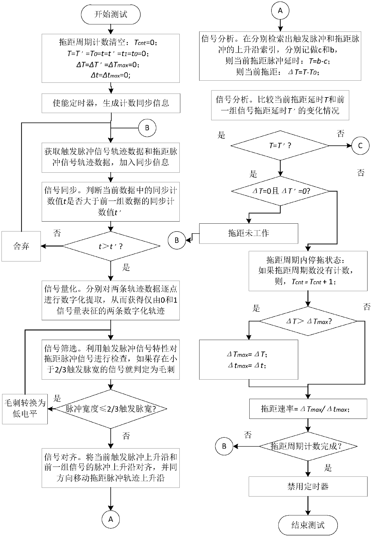
[0071] Below in conjunction with accompanying drawing and specific embodiment the present invention is described in further detail:

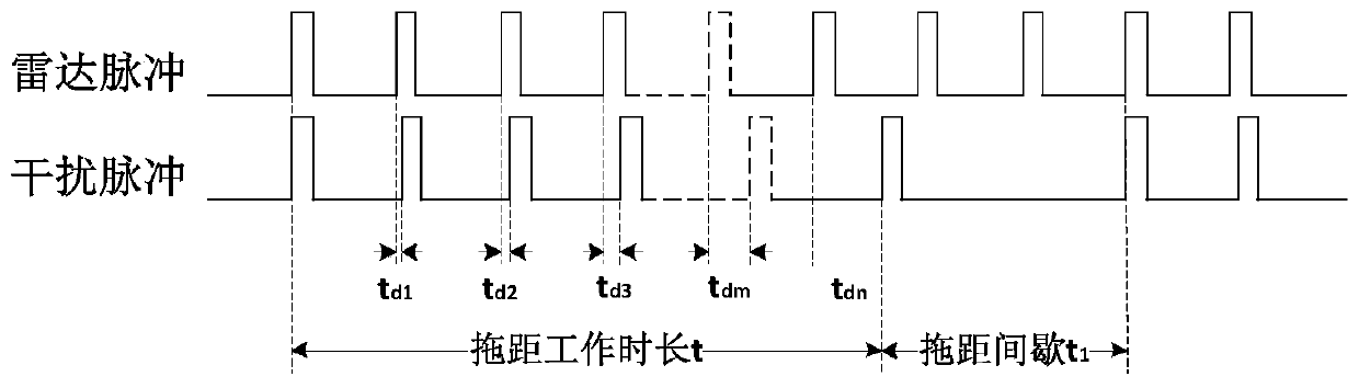
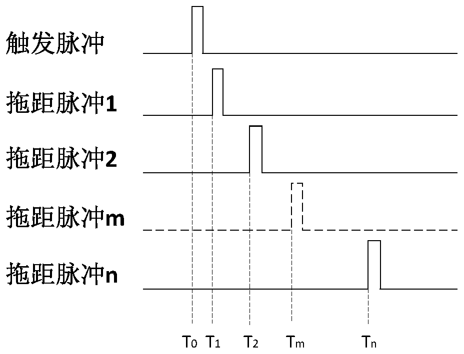
[0072] The present invention is an automatic test method for the tow rate of electronic countermeasure equipment, which can not only automatically test the tow rate parameters, but also use software to complete the drawing of the complete tow motion trajectory (referred to as "software tow afterglow" in the present invention) . It can be seen from formula (2) that the characterization of the trail speed needs to test two key parameters: trail distance ΔT and trail time Δt. Therefore, in order to accurately calculate the drag rate, the values ​​of these two parameters must be accurately obtained by means of automatic testing.

[0073] From figure 2 It can be seen that when the electronic countermeasure equipment is in the working state, ΔT is in a unidirectional positive growth state within a drag period. When the value of ΔT remains unchanged...


PUM


Abstract

The invention discloses an automatic test method for the drag rate of electronic countermeasure equipment, which belongs to the technical field of testing. The present invention adopts the automatic testing method of the drag rate parameter of the electronic countermeasure equipment, which effectively reduces the working intensity of the testing personnel, reduces the requirements for the working skills of the testing personnel, thereby reducing the testing cost; and reduces the operation and observation of the manual testing link. Uncertainty, using the computer's ability to acquire data and calculate data at high speed, can obtain accurate trail length and trail time, and the calculated test results have higher test accuracy; use software algorithms to describe the trail distance in a single job The complete motion trajectory of the cycle, the observation data is more intuitive and accurate.

Description

technical field [0001] The invention belongs to the technical field of testing, and in particular relates to an automatic testing method for the drag rate of electronic countermeasure equipment. Background technique [0002] Distance wave door towing (hereinafter referred to as "towing distance") is a self-defense technology of electronic countermeasure equipment. According to the principle of ranging by measuring the arrival time of radar echo pulses, it controls the increase between the launch of jammers and the radar echo pulses. volume delay t d The false echo pulse of the radar causes the target distance measured by the radar to be farther than the real target distance. The electronic countermeasure equipment simulates a "virtual target" at a certain distance from the enemy's radar by loading the range gate, and deceptively interferes with the enemy's radar system. It works as figure 1 shown. [0003] When the electronic countermeasure equipment implements jamming, ...

Claims


Application Information

Patent Timeline
Patent Type & Authority Patents(China)
IPC IPC(8): G01S7/40
Inventor 吴家亮周辉季汉国
Owner THE 41ST INST OF CHINA ELECTRONICS TECH GRP
Why Eureka
Try Eureka