
A device and method for self-assembly of micro-fluid stimulated micro-device

A self-assembly and micro-device technology, which is applied in semiconductor/solid-state device manufacturing, electrical components, circuits, etc., can solve the problems of low assembly efficiency, weakening the capillary force and surface tension of micro-components' self-gravity liquid bonding materials, and improving The success rate of assembly and the effect of solving the low efficiency of assembly

Active Publication Date: 2019-09-10
美泰(常州)控制系统有限公司
View PDF5 Cites 0 Cited by
  • Summary
  • Abstract
  • Description
  • Claims
  • Application Information

AI Technical Summary

Problems solved by technology

[0002] Drivers and display units in flat panel display (FPD) devices, high-density alignment assembly of LED chips, micro-control systems, optoelectronic smart array sensors, and electronic labels all require repeated precision assembly of large quantities of micro-components, fluid self-assembly technology The shape-matching alignment in the system has the ability to assemble a large number of micro-components in parallel and accurately in three-dimensional space. When under the action, it will randomly fall into the matching pits on the substrate. The traditional hydraulic pump valve drives the uniform flow of the solution. When the micro-component is close to the assembly point of the substrate, the inertial force of its movement will weaken the self-gravity and liquid bonding of the micro-component. Due to the capillary force and surface tension of the material, some micro-components will not be fully fitted with the substrate, and will fall into an energy trap, resulting in low assembly efficiency

Method used


Image

  • A device and method for self-assembly of micro-fluid stimulated micro-device

Examples


Embodiment 1

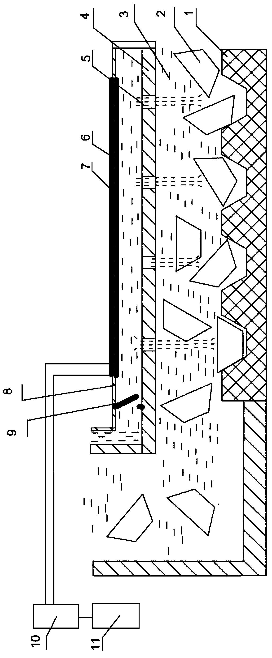
[0015] This embodiment provides a self-assembly device for micro-fluids to stimulate micro-devices, the structure of which is as follows: figure 1 Shown:

[0016] A substrate 1 such as silicon or glass has an array of pits of corresponding shapes etched out, and each pit is matched with a micro-element 2 of a specific shape manufactured from a silicon wafer. The micro-element 2 is carried by a carrier solution 3 and spaced The plate 4 is provided with a micro-spray array 5 corresponding to the pit on the substrate 1, and two curved piezoelectric vibrators (including the lower piezoelectric vibrator 6 and the upper piezoelectric vibrator 7) are attached to the metal elastic film 8 respectively, and the single The directional valve 9 , the partition 4 and the elastic film 8 form a closed cavity, and the fluid 3 can flow in from the one-way valve 9 and be ejected from the micro-spray array 5 . The two bending piezoelectric vibrators are controlled by a driving power source 10 an...

Embodiment 2

[0019] This embodiment provides a self-assembly method based on the self-assembly device described in Embodiment 1.

[0020] The excess microelements 2 are dispersed and suspended in the selected carrier solution 3, and can flow through the substrate 1 and the separator 4 under pressure, and the carrier solution in the separator 4 and the metal elastic film 8 does not contain the microelements 2, The computer 11 is programmed to control the vibration of the bending piezoelectric vibrator through the driving power supply 10. Due to the alternating bending vibration of the bending piezoelectric vibrator, the metal elastic film 8 is bent back and forth. When the metal elastic film 8 bends up and down, due to the one-way valve 9 and micro The role of the spray array 5, the fluid without the micro-element 2 can alternately flow in from the one-way valve 9 and spray out from the micro-spray array 5. After the computer 11 is programmed, the amplitude and frequency of the two bending p...


PUM


Abstract

The invention discloses a self-assembling device and method for micro-fluid excitation micro-components. The device includes a substrate and a spacer. The substrate has an array of etched pits. Each pit matches the shape of a micro-element. The micro-element is carried by a carrier solution. The spacer and the substrate form an assembly cavity. There are micro-jet arrays corresponding to the pits on the substrate, and two curved piezoelectric vibrators are attached to the elastic film respectively. The one-way valve, the partition and the elastic film form a closed cavity, and the solution flows in from the one-way valve and flows out from the one-way valve. The micro-jet array is ejected, and the two curved piezoelectric vibrators are controlled by the driving power supply and the computer. The present invention utilizes piezoelectric vibration to fluidly excite the micro-components on the substrate that are not fully fitted with the substrate, so that the energy obtained exceeds the energy trap formed when some micro-components cannot be fully fitted with the substrate, and the micro-components and the substrate are fully integrated. Fitting; fluid excitation adopts piezoelectric drive, which can be digitally adjusted in frequency and excitation intensity to improve the success rate of assembly.

Description

technical field [0001] The invention relates to an assembly device and method for micro components, in particular to an automatic assembly device and method for micro components. Background technique [0002] Drivers and display units in flat panel display (FPD) devices, high-density alignment assembly of LED chips, micro-control systems, optoelectronic smart array sensors, and electronic labels all require repeated precision assembly of large quantities of micro-components, fluid self-assembly technology The shape-matching alignment in the system has the ability to assemble a large number of micro-components in parallel and accurately in three-dimensional space. When under the action, it will randomly fall into the matching pits on the substrate. The traditional hydraulic pump valve drives the uniform flow of the solution. When the micro-component is close to the assembly point of the substrate, the inertial force of its movement will weaken the self-gravity and liquid bond...

Claims


Application Information

Patent Timeline
Patent Type & Authority Patents(China)
IPC IPC(8): H01L21/67
CPCH01L2224/95101
Inventor 刘天军刘青苑张杨
Owner 美泰(常州)控制系统有限公司
Learn More