Microstrip array antenna

A microstrip array and microstrip line technology, applied in the directions of antennas, antenna arrays, and individually powered antenna arrays, etc., can solve the problems of narrow frequency band, loose structure, beam offset, etc., to improve the gain, increase the compactness, and solve the The effect of beam shifting

Inactive Publication Date: 2018-01-30
NANJING UNIV OF SCI & TECH
View PDF1 Cites 8 Cited by
  • Summary
  • Abstract
  • Description
  • Claims
  • Application Information

AI Technical Summary

Problems solved by technology

[0004] The purpose of the present invention is to provide a microstrip array antenna to solve the problems of beam offset, narrow frequency band, and loose structure caused by traditional microstrip array antennas using T-junction splitters.

Method used


Image

  • Microstrip array antenna
  • Microstrip array antenna
  • Microstrip array antenna

Examples


Embodiment Construction

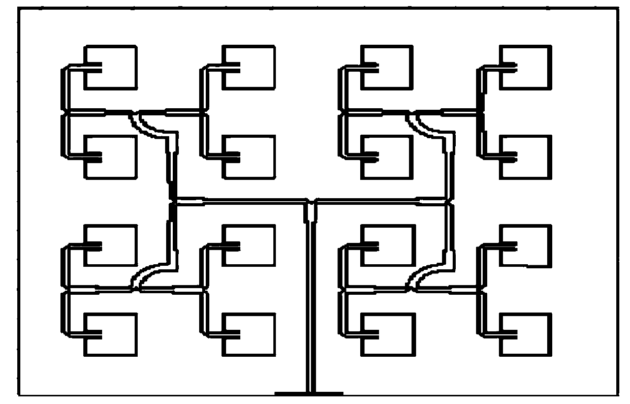
[0015] combine figure 1 , a microstrip array antenna, including a dielectric substrate and eight groups of radiating units arranged on the dielectric substrate, each group of radiating units includes two sub-radiating units of the same frequency band, and sixteen sub-radiating units are arranged on the dielectric substrate in a 4×4 aligned in the same direction;

[0016] The feed network between the two sub-radiating units in each group is a first one-to-two T-junction power divider, and the two output ports of each first one-to-two T-junction power divider are connected by a microstrip line For the two corresponding sub-radiating units, every two first one-to-two T-junction power divider input ports are connected to a second one-to-two T-junction power divider output port through a microstrip line, and each two second one-to-two T-junction power divider output ports The input port of the split-two T-junction splitter is connected to the output port of a third one-split-two T...


PUM


Abstract

The invention discloses a microstrip array antenna which comprises a dielectric substrate and eight groups of radiating elements arranged on the dielectric substrate. Each group of radiating elementscomprises two sub-radiating elements with the same frequency band. The sixteen radiating elements are arranged on the dielectric substrate along the same direction according to a 4*4 way, and are connected with the entire feed network in a cascaded way in order to ensure 16-equal divisions. The microstrip array antenna changes the design of the feed network, increases antenna gain, and well solvesbeam deviation and a waste of overall antenna space caused by just using a single T-junction power divider.

Description

technical field [0001] The invention relates to microstrip antenna technology, in particular to a microstrip array antenna. Background technique [0002] Microstrip antenna is the most widely used antenna in recent years. Compared with traditional antenna, it has many irreplaceable advantages. It is small in size, light in weight, and has a planar structure, so it is easy to combine with missiles, satellites and other carriers to form a conformal structure. Not only that, the microstrip antenna also has the characteristics of compact structure and stable performance. It is widely used in mass production of printed circuit technology, and it is convenient to realize many functions such as dual frequency band and dual polarization. However, microstrip antennas also have shortcomings such as narrow frequency band, large loss, and small power capacity, so they are limited in practical applications. In order to overcome these shortcomings, microstrip antennas are usually formed ...

Claims


Application Information

Patent Timeline
Patent Type & Authority Applications(China)
IPC IPC(8): H01Q21/00H01Q21/06
Inventor 彭树生毛誉杰吴礼李文超张竣昊
Owner NANJING UNIV OF SCI & TECH
Why Eureka
Try Eureka