
Rotary forming device for concrete prefabricated part

A technology of concrete prefabricated parts and forming devices, which is applied in the direction of supply devices, ceramic molding machines, manufacturing tools, etc., and can solve problems such as low production efficiency, long production cycle of concrete prefabricated parts, and high labor intensity of operators

Pending Publication Date: 2018-02-02
WUJIANG CITY MINGGANG ROAD & BRIDGE
View PDF7 Cites 3 Cited by
  • Summary
  • Abstract
  • Description
  • Claims
  • Application Information

AI Technical Summary

Problems solved by technology

Vibrating the prefabricated form filled with concrete through a vibrating table can move the sand, stone, and cement in the concrete, thereby filling the pores and discharging air bubbles, but this process often requires a long time to vibrate the concrete, resulting in The production cycle is long, the production efficiency is low, and the concrete is often piled up after being poured into the prefabricated mold. It needs to be manually paved to make the concrete fill the prefabricated mold. The manual paving of the concrete takes a long time, resulting in high labor intensity for the operator and low production efficiency. Low

Method used


Image

  • Rotary forming device for concrete prefabricated part
  • Rotary forming device for concrete prefabricated part
  • Rotary forming device for concrete prefabricated part

Examples


Embodiment Construction

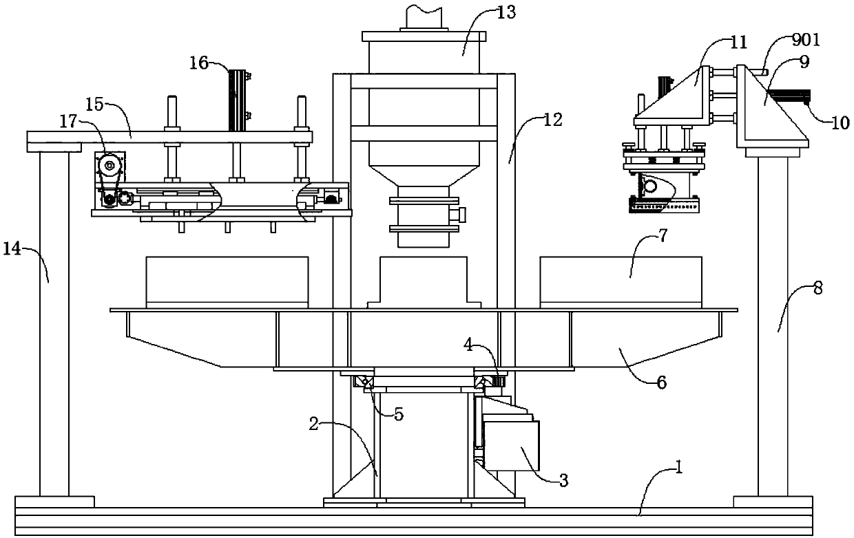
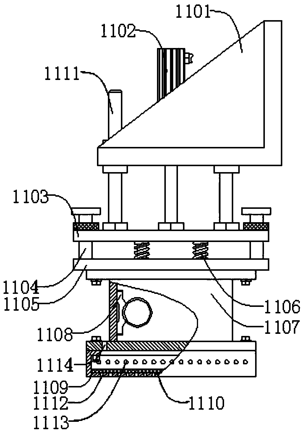
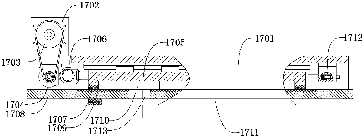
[0024] likefigure 1 , figure 2 , image 3 , Figure 4 As shown, a rotary concrete precast molding device includes a base 1, a stand 2, a servo motor 3, a gear 4, a slewing bearing 5, a turntable 6, a prefabricated mold 7, a right column 8, a first bracket 9, a second A cylinder 10, a pre-press vibration mechanism 11, a support 12, a feed bin 13, a left column 14, a top plate 15, a second cylinder 16, and a spreading mechanism 17, the stand 2 is located at the center of an end on the base, and the The stand 2 is threadedly connected with the base 1, the servo motor 3 is located at the outer upper end of the stand 2, the servo motor 3 is threaded with the stand 2, the gear 4 is located at the upper end of the servo motor 3, and the The gear 4 is keyed to the servo motor 3, the slewing support 5 is located at the upper end of the stand 2 and on the side of the gear 4, the slewing support 5 is screwed to the stand 2 and meshed with the gear 4, and the turntable 5 is located at...


PUM


Abstract

The invention discloses a rotary forming device for a concrete prefabricated part. The rotary forming device comprises a base, a vertical seat, a servo motor, a gear, a rotating support, a rotary table, prefabricating moulds, a right vertical column, a first bracket, a first air cylinder, a pre-pressing and vibration mechanism, a support, a material bin, a left vertical column, a top plate, a second air cylinder and a paving mechanism. The servo motor works, concrete is put into the prefabricating moulds when the prefabricating moulds rotate to the position under the material bin, and the prefabricating moulds move to the position under the paving mechanism; the second air cylinder works, material pushing heads are inserted into the prefabricating moulds, and the paving mechanism drives the material pushing heads to make reciprocating motion to flatten the concrete; and then the prefabricating moulds move to the lower end of the pre-pressing and vibration mechanism, and the pre-pressing and vibration mechanism works to pre-press and vibrate the concrete. The rotary forming device is simple in structure; the concrete can be flattened, pre-pressed and vibrated automatically, so thatthe prefabricating moulds are filled with the concrete rapidly and fully; and the concrete is combined rapidly because of being pressed so as to exhaust air, thus, the comprehensive quality of the concrete prefabricated part is effectively improved, the automation degree is high, and the production efficiency is high.

Description

technical field [0001] The invention relates to a mechanical device, in particular to a rotary concrete prefabricated part forming device. Background technique [0002] Concrete prefabricated parts refer to various building components and projects with a certain shape obtained by mixing, forming and curing cement, sand, stone and water (with or without admixtures and admixtures) in a certain proportion. Prefabricated parts, which are widely used in civil engineering such as roads, bridges, and buildings. The processing flow of concrete prefabricated parts is generally as follows: first place various components in the mixer for mixing, then manually pour the mixed concrete into the prefabricated mold, and then prevent the prefabricated mold filled with concrete from vibrating on the vibrating table. Finally, after the concrete is cured, the prefabricated mold is removed to obtain the concrete prefabricated part. Vibrating the prefabricated form filled with concrete through ...

Claims


Application Information

Patent Timeline
IPC IPC(8): B28B5/08B28B3/02B28B13/02
CPCB28B3/022B28B5/08B28B13/0215B28B13/0295
Inventor 赵良姚秋红李小敏金伟英
Owner WUJIANG CITY MINGGANG ROAD & BRIDGE
Learn More