Load-uniformizing device for steel rail translation system

A technology of translation system and rail, which is applied in the direction of conveyor control device, transportation and packaging, conveyor, etc., can solve the long-term problem; the second is that the mechanical and electrical devices are placed below the floor, and it is impossible to arrange the mechanical and electrical components of the rail lateral movement system. Installation and layout of the rail traverse system and other issues to achieve the effect of eliminating slippage accidents, reducing the number of spare parts, and reducing the failure rate

Active Publication Date: 2018-02-02
上海瑞纽机械股份有限公司
View PDF8 Cites 0 Cited by
  • Summary
  • Abstract
  • Description
  • Claims
  • Application Information

AI Technical Summary

Problems solved by technology

[0004] In view of the above problems, the current rail traversing system is a better solution. The current rail traversing system has certain requirements on the site. For example, the elevation of the rail conveying line and the floor is required to be ≥1000mm, otherwise the rail traversing cannot be arranged. Mechanical and electrical installation of the system
However, due to the lack of understanding of the above situation at the beginning of the construction of the welding rail base, the site conditions vary greatly, and it is difficult to solve it with a single mode of rail traverse. The elevation is only 300mm, so it is impossible to arrange the rail traversing system on the floor. If the mechanical and electrical devices of the rail traversing system are lowered by digging pits, firstly, the workload of earthwork will be heavy and the downtime will be long; and electrical installations are placed below the floor, drainage and future maintenance are big problems

Method used


Image

  • Load-uniformizing device for steel rail translation system
  • Load-uniformizing device for steel rail translation system
  • Load-uniformizing device for steel rail translation system

Examples


Embodiment Construction

[0049] The technical solutions of the present invention will be further described below in conjunction with the accompanying drawings and embodiments.

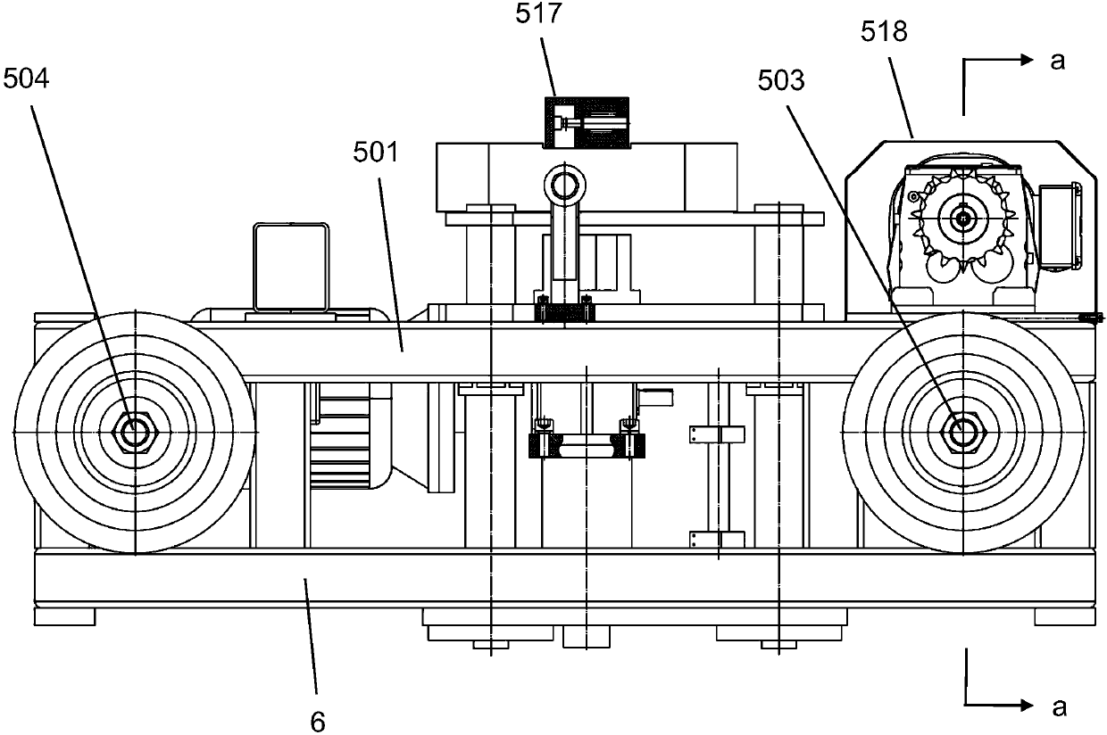
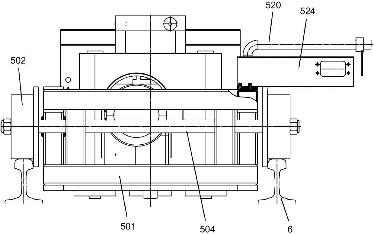
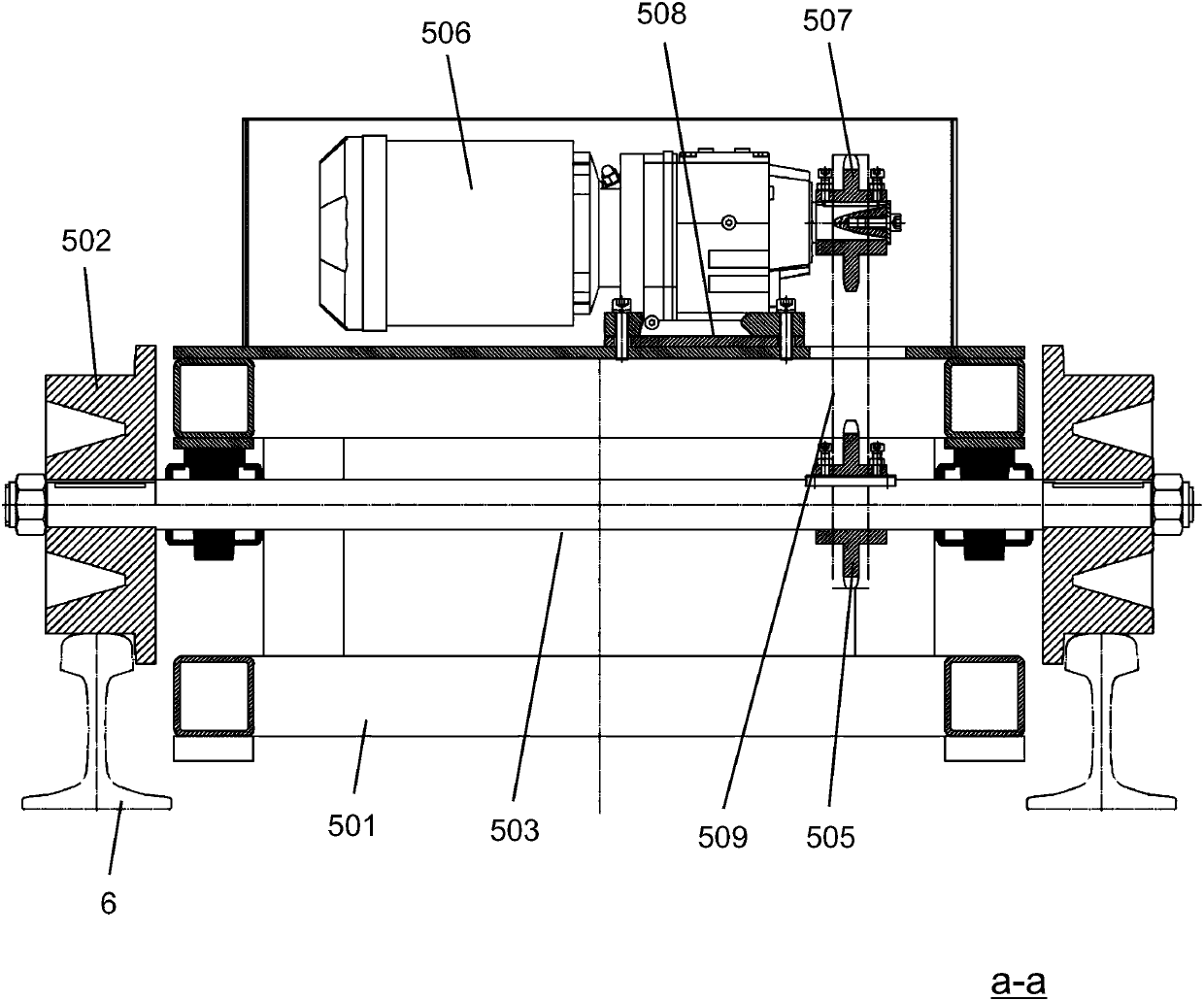
[0050] Please combine Figure 1 to Figure 8As shown, a load equalizing device of a rail translation system provided by the present invention, the rail translation system includes: a general control module, a first delivery track 1, a second delivery track 2 arranged in parallel with the first delivery track 1, and a device There are several sets of traversing mechanisms on the first conveying track 1 and the second conveying track 2, and the general control module is used to synchronously control each set of traversing mechanisms. In this embodiment, 8 sets of traversing mechanisms are used, and the rail 3 is 100m in length. rails.

[0051] Preferably, the traversing mechanism includes: a sub-control unit, a carrying unit, a translation unit and a lifting unit, and the sub-control unit is used to receive the synchronization c...


PUM


Abstract

The invention discloses a load-uniformizing device for a steel rail translation system. The steel rail translation system comprises a master control module, a first conveying rail, a second conveyingrail arranged in parallel to the first conveying rail, and a plurality of transverse travelling mechanisms arranged on the first conveying rail and the second conveying rail, wherein each transverse travelling mechanism comprises a sub-control unit, a bearing unit, a translation unit and a lifting unit; each translation unit comprises a transverse travelling trolley and a guide rail; each transverse travelling trolley is movably arranged on the corresponding guide rail; each transverse travelling trolley comprises a frame component, as well as a speed reduction component, a lifting component and an induction component which are arranged on the frame component; wheels are arranged at the outer side of each frame component; each frame component moves on the corresponding guide rail through the corresponding wheels; each speed reduction component is used for driving the corresponding wheels to rotate; each induction component is used for inducing the ascending height and the moving distance of the corresponding transverse travelling trolley; and each lifting component is used for bearing steel rails. The steel rail translation system disclosed by the invention is applicable to the case of a small distance of not greater than 1000mm between a steel rail conveying line on a welded rail site and a ground elevation.

Description

technical field [0001] The invention relates to a rail translation system used for rail conveying lines and floors in railway bureau rail welding bases, especially suitable for small spacing, and also suitable for other lifting operations. More specifically, The utility model relates to a load equalizing device of a rail translation system. Background technique [0002] With the vigorous construction of high-speed railways, the demand for long rails has increased, and higher requirements have been placed on the efficiency of rail welding plants. The rails of the rail welding base are unloaded from the truck by the gantry crane to the unloading storage area, and then the rails are hoisted into groups by the gantry crane (currently, 7 groups of gantry cranes are commonly used in domestic rail welding factories) to the rail storage platform. On the storage table, the rails are transferred to the rail conveying line individually, so that the rails enter the subsequent grinding,...

Claims


Application Information

Patent Timeline
Patent Type & Authority Applications(China)
IPC IPC(8): B65G47/52B65G35/06B65G43/00
CPCB65G35/06B65G43/00B65G47/52
Inventor 宋正忠陈光军蔡龙庆王明月
Owner 上海瑞纽机械股份有限公司
Why Eureka
Try Eureka