Silenced high-speed centrifugal fan
A high-speed centrifugal and fan technology, used in mechanical equipment, machines/engines, liquid fuel engines, etc., can solve the problems of difficult processing, high assembly requirements, and low processing costs of centrifugal fans, and achieve improved flow field dynamics. The effect of reducing large-scale vortex and increasing fan pressure
- Summary
- Abstract
- Description
- Claims
- Application Information
AI Technical Summary
Problems solved by technology
Method used
Image
Examples
Embodiment 1
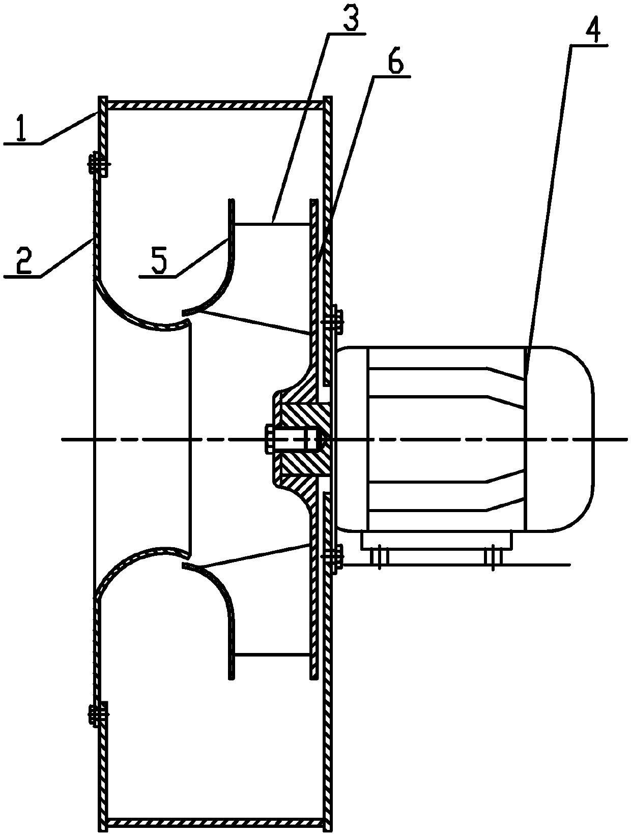
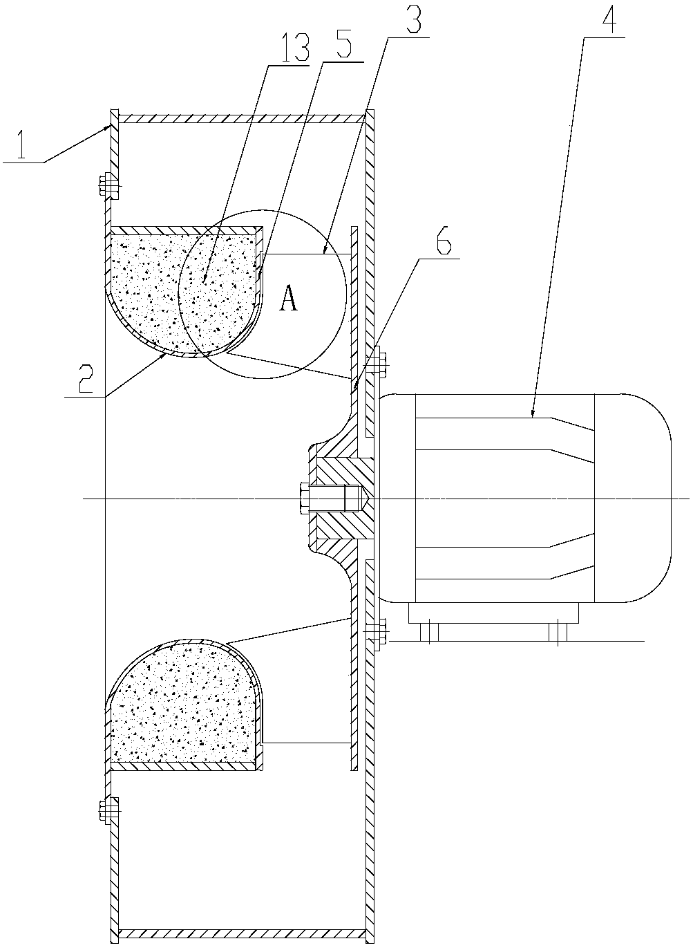
[0058] A noise-absorbing high-speed centrifugal fan, such as figure 2 As shown, it includes a casing 1, an air inlet 2, a blade 3, an impeller front cover 5, an impeller rear cover 6 and a motor 7.
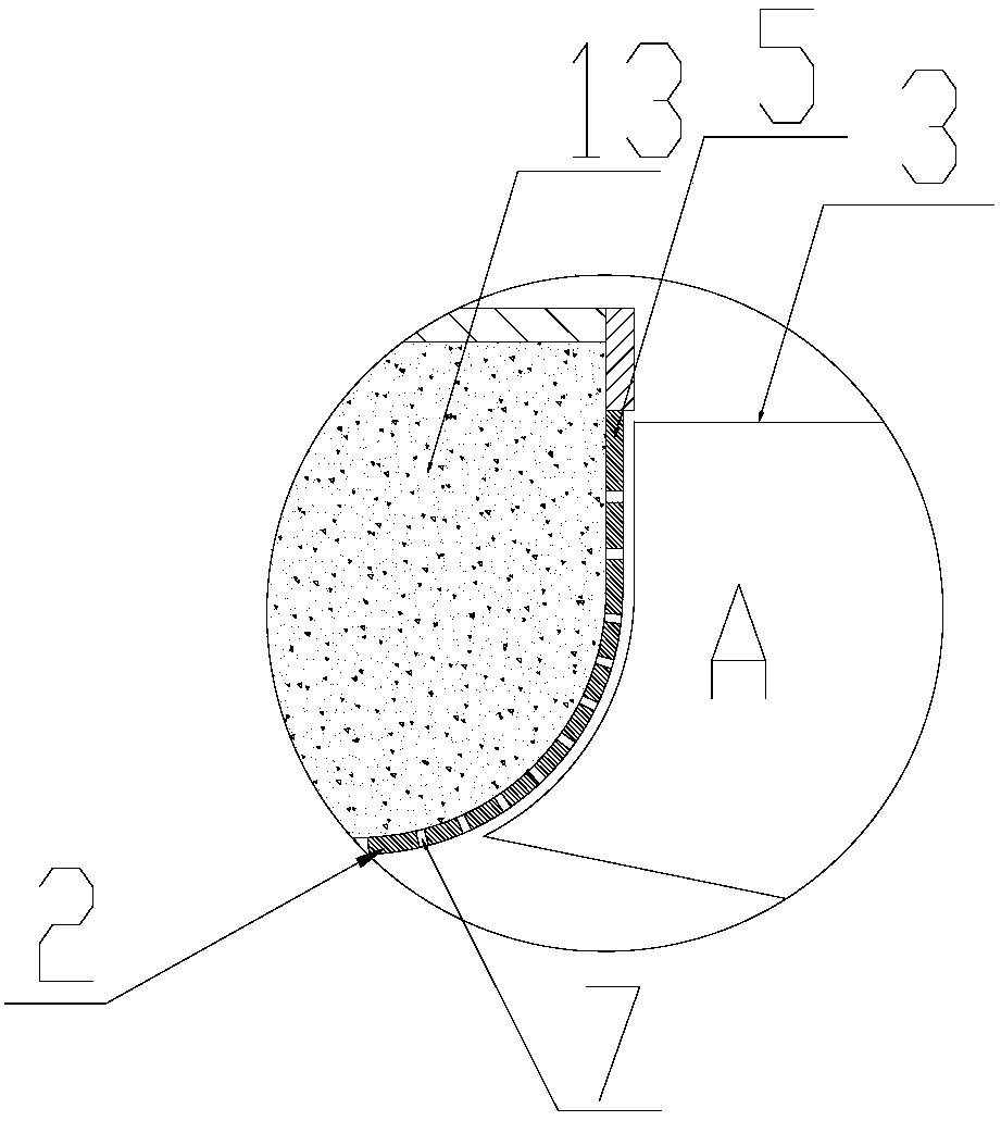
[0059] The casing 1 is a hollow spiral asymmetric structure with an opening on the bottom surface. The rear side plate of the casing 1, that is, the unopened surface, is fixedly connected to the mounting plate of the motor 4 through bolts. The opening position corresponds to the conical arc-shaped air inlet 2, and the air inlet 2. It is connected with the front cover plate 5 of the annular impeller. The front cover plate 5 of the impeller completely covers the impeller composed of the blades 3. The diameter of the impeller is 250mm, and the blades 3 are arc-shaped. The distance between the two opposite surfaces of the cover plate 5 and the blade 3 is 1mm, and the surface opposite to the blade of the front cover plate of the impeller is provided with an annular protrusion 15 surro...
Embodiment 2
[0063] A noise-absorbing high-speed centrifugal fan, the structure of which is basically the same as that of Embodiment 1, the difference is that there is no ring-shaped protrusion surrounding the blade on the surface of the impeller front cover plate opposite to the blade, and the impeller front cover plate, air inlet and cylinder Welded with iron plate, the distance between the two opposite surfaces of the impeller front cover plate and the blade is 0.9mm, the blade is airfoil type, the thickness of the metal plate is 0.95mm, the perforation rate is 30%, and the aperture of the through hole is 6mm.
[0064] The speed of the noise-absorbing high-speed centrifugal fan is 7000rpm, and the efficiency is 75%. It has been verified that the noise-absorbing high-speed centrifugal fan of the present invention has low processing difficulty, low processing cost, high overall strength, can meet the requirements of high speed, reasonable design, and low assembly requirements; compared wit...
Embodiment 3
[0066] A noise-absorbing high-speed centrifugal fan, the structure of which is basically the same as that of Embodiment 2, the difference is that a sheet-shaped reinforcing ring is fixed on the surface opposite the blade and the front cover of the impeller, and the outer edge of the reinforcing ring intersects the outer edge of the blade. The outer edge refers to the edge farthest from the central axis of the motor output shaft. The width of the reinforcement ring is 5mm. The reinforcement ring, blades and impeller rear cover are integrally milled. The distance between them is 0.8mm, the thickness of the metal plate is 0.85mm, the perforation rate is 25%, and the diameter of the through hole is 7mm.
[0067] The speed of the noise-absorbing high-speed centrifugal fan is 7500rpm, and the efficiency is 72.5%. It has been verified that the noise-absorbing high-speed centrifugal fan of the present invention has low processing difficulty, low processing cost, high overall strength,...
PUM
| Property | Measurement | Unit |
|---|---|---|
| Thickness | aaaaa | aaaaa |
| Aperture | aaaaa | aaaaa |
| Width | aaaaa | aaaaa |
Abstract
Description
Claims
Application Information
 - R&D
- Intellectual Property
- Life Sciences
- Materials
- Tech Scout
- Unparalleled Data Quality
- Higher Quality Content
- 60% Fewer Hallucinations
Browse by: Latest US Patents, China's latest patents, Technical Efficacy Thesaurus, Application Domain, Technology Topic, Popular Technical Reports.
© 2025 PatSnap. All rights reserved.Legal|Privacy policy|Modern Slavery Act Transparency Statement|Sitemap|About US| Contact US: help@patsnap.com


