Improved type synchronous mechanism and hybrid power transmission thereof

A synchronous mechanism and hybrid technology, applied in the direction of mechanical drive clutches, clutches, power units, etc., can solve the problems of long synchronization time, difficulty in shifting, and the overall efficiency of the transmission is reduced, and achieves the effect of low cost.

Pending Publication Date: 2018-02-02
SHANGHAI AUTOMOBILE GEAR WORKS
View PDF0 Cites 1 Cited by
  • Summary
  • Abstract
  • Description
  • Claims
  • Application Information

AI Technical Summary

Problems solved by technology

The existing hybrid transmissions improved on the basis of mechanical automatic transmissions all have the following defects: 1) the motor cannot be disengaged when the vehicle is driven by the pure engine, which reduces the overall efficiency of the transmission; The large inertia of the synchronous motor rotor leads to long synchronization time and difficulty in gearing; 3) It is impossible to use only one motor to realize parking and charging, etc.

Method used


Image

  • Improved type synchronous mechanism and hybrid power transmission thereof
  • Improved type synchronous mechanism and hybrid power transmission thereof
  • Improved type synchronous mechanism and hybrid power transmission thereof

Examples


Embodiment 1

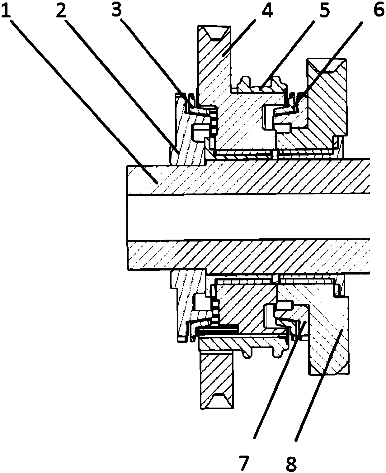
[0022] like figure 1 As shown, the improved synchronizing mechanism of this embodiment includes: the charging gear coupling tooth 2 and the EV gear driving gear 8 arranged oppositely, and the charging block synchronizing ring 3 and the motor transmission gear sleeved on the charging gear coupling tooth 2 in sequence. 4 and the synchronous gear sleeve 5 and the EV gear joint tooth 7 and EV gear synchronizing ring 6 which are sequentially sleeved on the EV gear driving gear 8, when the synchronizing gear sleeve 5 is turned to the left, it passes through the charging gear synchronizing ring 3 and is connected with the charging gear. When the gear tooth 2 is combined, the torque can be transmitted between the motor transmission gear 4 and the shaft 1; the synchronous gear sleeve 5 is dialed to the right, and after passing through the EV gear synchronizing ring 6, it is combined with the EV gear combining tooth 7, and the torque can be transmitted in the motor. The transmission bet...

Embodiment 2

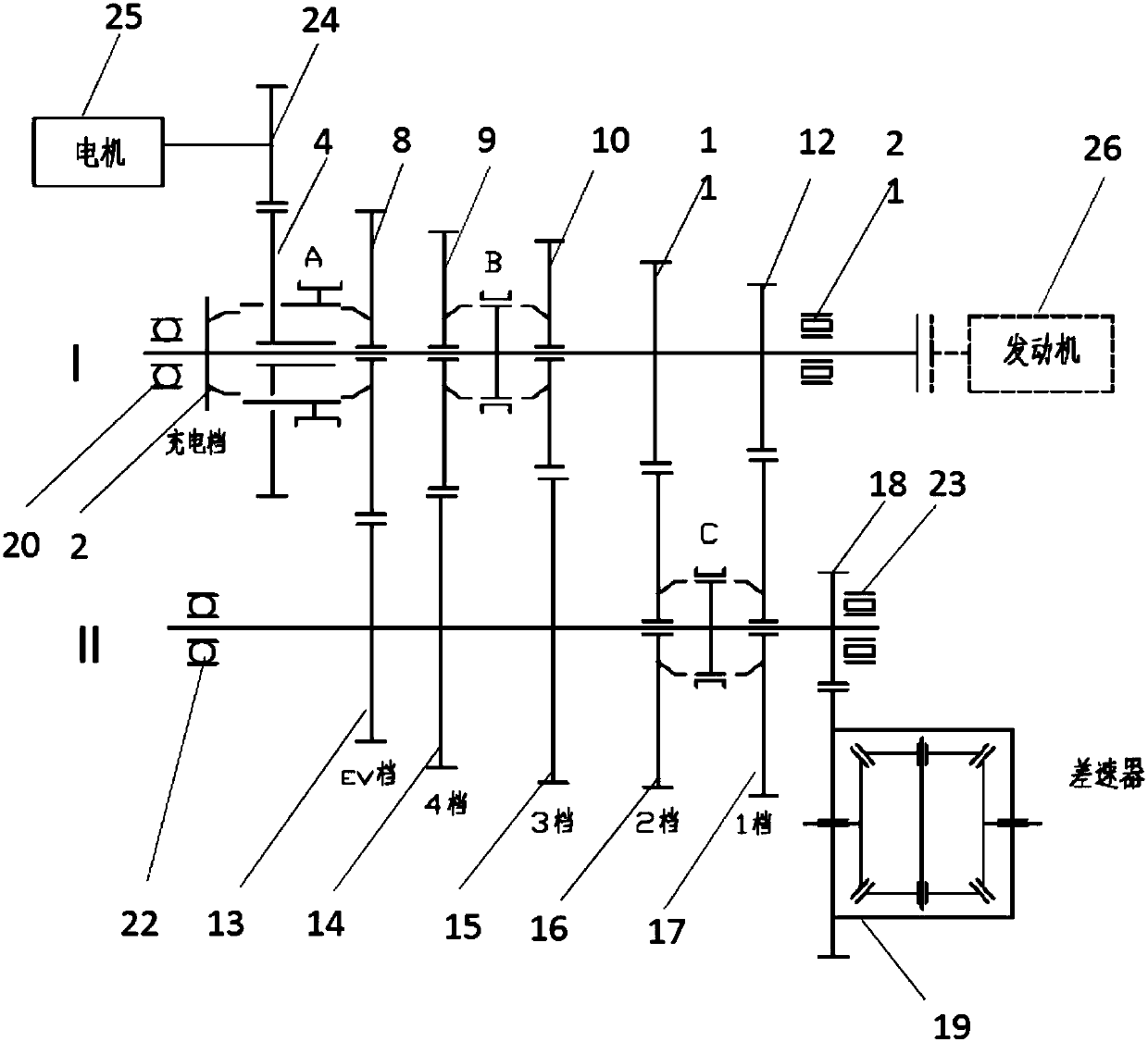
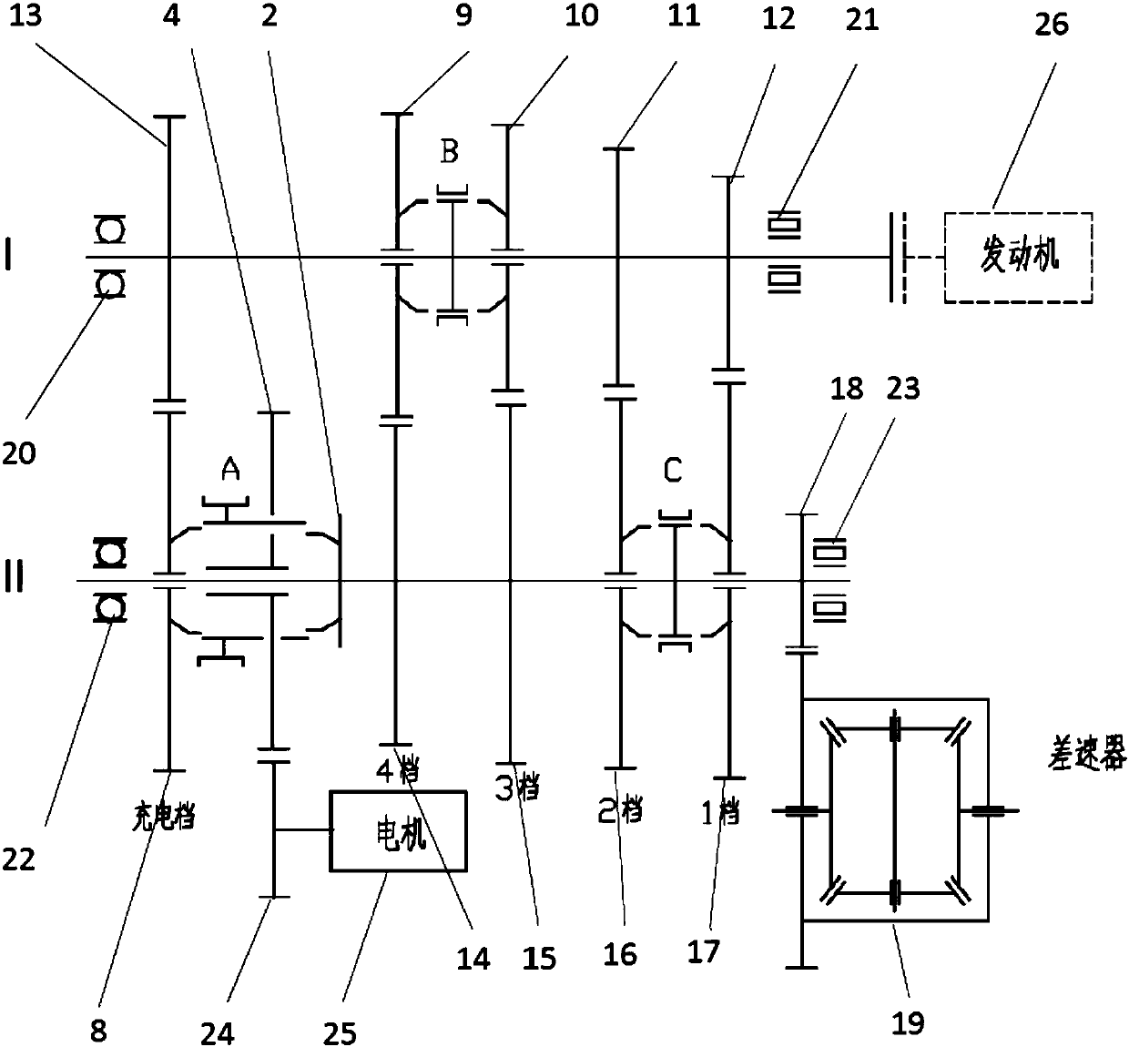
[0042] like image 3 As shown, this embodiment relates to a transmission for hybrid power based on the above-mentioned improved synchronous mechanism, including: a second synchronous mechanism B arranged on the input shaft I, connected with the motor transmission gear 4 and sleeved on the output shaft II The improved synchronous mechanism A and the third synchronous mechanism C, the input shaft is successively provided with an EV gear driven gear 13, a fourth gear driving gear 9, a third gear driving gear 10, a second gear driving gear 11 and a first gear driving gear 12, The output shaft is successively provided with a fourth gear driven gear 14, a third gear driven gear 15, a second gear driven gear 16, a first gear driven gear 17 and a main reduction driving gear 18, wherein: the EV gear driven gear 13 and the improved The driving gears of the EV gear of the type synchronous mechanism are meshed, the driving gears from the fourth gear to the first gear are meshed with the c...


PUM


Abstract

An improved synchronous mechanism and a transmission for hybrid power thereof, the synchronous mechanism includes: a charging gear coupling tooth and an EV gear driving gear arranged oppositely, and a charging gear synchronous ring and a motor transmission gear which are sequentially sleeved on the charging gear coupling teeth and the synchronous gear sleeve and the EV gear combined teeth and the EV gear synchronous ring which are sleeved on the EV gear driving gear in sequence. On the basis of the original mechanical automatic transmission structure, the present invention connects the drive motor in an ingenious manner, and manipulates the transmission direction of the motor power through the synchronous mechanism, so that the engine power and the motor power can be independently controlled and mutually controlled during the transmission process. Non-interference, and at the same time, when needed, they can complement each other.

Description

technical field [0001] The invention relates to a technology in the field of hybrid electric vehicles, in particular to an improved synchronizing mechanism and a transmission for hybrid electric vehicles. Background technique [0002] The design principle, production process and technology of manual transmission have been mature and stable for a long time. The addition of motor power can make up for the loss of engine power during the shifting process of mechanical automatic transmission, and can make full use of the high efficiency and low cost of manual transmission. The advantage is the solution of choice for many hybrid models. The existing hybrid transmissions improved on the basis of mechanical automatic transmissions all have one of the following defects: 1) the motor cannot be disengaged when the vehicle is driven by a pure engine, which reduces the overall efficiency of the transmission; 2) the synchronizer needs to be in gear The large inertia of the rotor of the ...

Claims


Application Information

Patent Timeline
Patent Type & Authority Applications(China)
IPC IPC(8): F16D23/02F16H3/12B60K6/547
CPCF16D23/02B60K6/547F16H3/12F16H2200/0043F16H2200/2038
Inventor 高彬陈洁婧杨志峰
Owner SHANGHAI AUTOMOBILE GEAR WORKS
Why Eureka
Try Eureka