Method for simultaneously testing stiffness, flexibility and drapability of fabric

A drapable, rigid-flexible technology, applied in the field of textile and garment performance testing, can solve the problems of many fabric samples, long time consumption, large test workload, etc., and achieve accurate and reliable results, simple and convenient process, and shortened test cycle. Effect

Active Publication Date: 2018-02-02
通标标准技术服务(常州)有限公司
9 Cites 6 Cited by

AI-Extracted Technical Summary

Problems solved by technology

[0002] The rigidity, flexibility and drape of fabrics are important properties that affect the appearance of fabrics, and it is particularly important to accurately test them. The existing fabric rigidity, flexibi...

Abstract

The invention discloses a method for simultaneously testing stiffness, flexibility and drapability of a fabric. The method comprises the following steps: step one, tailoring a to-be-tested fabric intoa first rectangular sample and a second rectangular sample, and successively carrying out step two, step three, step four, step five and step six if i equals to 1, 2; step two, placing the ith rectangular sample on a fabric fixing device; step three, photographing the fabric by an image photographing device; step four, acquiring point cloud and a three-dimensional point cloud coordinate array byImageware software; step five, storing the three-dimensional point cloud coordinate array into a data file in an asc formate, and reopening the three-dimensional point cloud coordinate array in Imageware; step six, carrying out image and feature extraction in the Imageware software; and step seven, solving the flexural rigidity E and fabric draping coefficient of the to-be-tested fabric.

Application Domain

Technology Topic

Data fileFlexural rigidity +6

Image

  • Method for simultaneously testing stiffness, flexibility and drapability of fabric
  • Method for simultaneously testing stiffness, flexibility and drapability of fabric
  • Method for simultaneously testing stiffness, flexibility and drapability of fabric

Examples

  • Experimental program(1)

Example Embodiment

[0028] The present invention will be further described below in conjunction with the drawings.
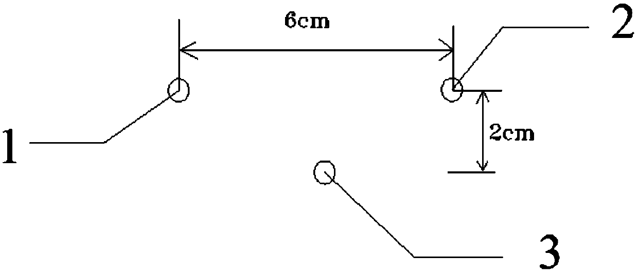
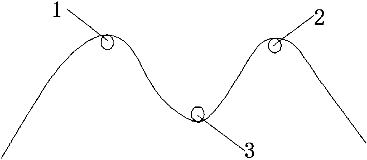
[0029] Such as figure 1 As shown, a fabric fixing device used in a method for testing fabric rigidity, flexibility and drape at the same time includes a first pin 1, a second pin 2, a third pin 3 and an image capturing device. The image pickup device uses a digital camera with more than 10 million pixels. The first pin 1, the second pin 2 and the third pin 3 are all arranged horizontally and arranged in an isosceles triangle (that is, the projections of the first pin, the second pin and the third pin on the plane perpendicular to the axis of the first pin respectively Are the three vertices of an isosceles triangle.). The first pin 1 and the second pin 2 are spaced 6 cm apart and have the same height. The third pin 3 is located 2 cm below the line connecting the first pin 1 and the second pin 2 and on the vertical line of the line connecting the first pin 1 and the second pin 2.
[0030] The method for simultaneously testing the rigidity, flexibility and drape of the fabric is as follows:
[0031] Step 1. After ironing the fabric to be tested flat, cut it into a first rectangular sample and a second rectangular sample. Both the first rectangular sample and the second rectangular sample are 15cm×2.5cm rectangles. The length of the first rectangular sample is set along the warp of the fabric to be tested. The length of the second rectangular sample is set along the weft direction of the fabric to be tested. Draw marking lines on the first rectangular sample and the second rectangular sample. The mark line is the connection between the midpoints of the two length sides. i=1, 2, perform steps 2, 3, 4, 5, and 6 in sequence.
[0032] Step two, such as figure 2 As shown, the i-th rectangular sample is placed on the fabric fixing device. Make the i-th rectangular sample pass under the third pin 3, pass over the first pin 1 and the second pin 2, and the marking line is in contact with the third pin 3. At this time, the length side of the i-th rectangular sample is M-shaped.
[0033] Step 3: Use the image capturing device to photograph the i-th rectangular sample placed on the fabric fixing device from a direction parallel to the width side of the i-th rectangular sample. Get a photo of the fabric.
[0034] Step 4. Import the fabric photo into Imageware software; perform the “create point” processing on the fabric photo to obtain the point cloud arranged along the i-th rectangular sample in the fabric photo (ie along the length of the i-th rectangular sample) A collection of discrete points set on the edge) and a three-dimensional point cloud coordinate array (ie, the collection of all point coordinates in the point cloud). The operation steps are to first click "Create", "Point", then click "Edit", "Parameter Setting", and set "Yellow Solid Ball" as the point display form in "Parameter Setting".
[0035] Step 5. Save the 3D point cloud coordinate array as a data file in asc format, and reopen it in Imageware. At this time, only the point cloud distribution map corresponding to the M-shaped curve is displayed, and the fabric photo is not displayed.
[0036] Step 6. Perform image and feature extraction in Imageware software.
[0037] ① Fit the auxiliary curve according to the three-dimensional point cloud coordinate array: the operation steps are to click "build", "build curve from point cloud", and "uniform curve" in turn. Enter 18 in the "Linear Order" column and 10 in the "Span" column. Select “Fixed” in the “Start Point” and “End Point” columns, so that the two ends of the auxiliary curve to be fitted coincide with the two ends of the M-shaped curve respectively. Click the "Apply" button. While obtaining the auxiliary curve, the shape of the point cloud is closer to the M shape formed by the i-th rectangular sample in the fabric photo.
[0038] When the "linear order" is below the 18th order, the point cloud fits with the M shape formed by the i-th rectangular sample in the fabric photo; when the "linear order" is above the 18th order, the greater the order, the point cloud The smaller the fit with the M shape formed by the i-th rectangular sample in the fabric photo. The fit is the degree that the shape of the point cloud approximates the M shape formed by the i-th rectangular sample in the fabric photo. Therefore, when the fit is maximized, the shape of the point cloud is the same as the M-shape formed by the i-th rectangular sample in the fabric photo. The degree of similarity is greatest. Therefore, the "Linear Order" column is set to 18.
[0039] ②Build a tolerance curve based on the three-dimensional point cloud coordinate array: the operation steps are to click "build", "build curve from point cloud", and "tolerance curve" in turn. Enter 0.1000 in the "Tolerance" column and 18 in the "Order" column. Set the "Deviation Mode" column as the average deviation, and click the "Apply" button to get the tolerance curve constructed from the 3D point cloud coordinate array. And get the tolerance curve feature size M i.
[0040] ③Assess straightness L i :The operation steps are to click “evaluate”, “point cloud characteristics”, and “straightness” in turn to get straightness L i. Straightness will calculate and display the straightness of the shape represented by the 3D point cloud coordinate array. This function calculates and displays the straightness of the shape represented by the three-dimensional point cloud coordinate array, and is represented by the radius of a boundary cylinder containing the shape represented by the entire three-dimensional point cloud coordinate array. The software automatically places the boundary cylinder at the position that minimizes the radius of the boundary cylinder. At this time, the boundary cylinder is a cylinder that completely envelops the tolerance curve and has the smallest diameter (that is, the boundary cylinder is in contact with the two end points and two peak points of the tolerance curve, and the vertical distance between the end point of the tolerance curve and the peak point is equal to the boundary The diameter of the cylinder). The radius of the boundary cylinder is the straightness L i.
[0041] ④Evaluate the curvature and curve curvature of the 3D point cloud coordinate array: The operation steps are to click "Evaluate", "Curvature", "Point Cloud Curvature/Curve Curvature" in turn to obtain the adjacent size N of the point cloud curvature distribution i. The adjacent size of the point cloud curvature distribution shows the distribution relationship between the large curvature and the small curvature in the shape represented by the 3D point cloud coordinate array, that is, the point at the most curved part and the point closest to the straight line in the shape represented by the 3D point cloud coordinate array The curvature is poor.
[0042] Step 7. Find the bending stiffness E of the fabric to be tested:
[0043]
[0044] Find the fabric drape coefficient F:
[0045]

PUM

no PUM

Description & Claims & Application Information

We can also present the details of the Description, Claims and Application information to help users get a comprehensive understanding of the technical details of the patent, such as background art, summary of invention, brief description of drawings, description of embodiments, and other original content. On the other hand, users can also determine the specific scope of protection of the technology through the list of claims; as well as understand the changes in the life cycle of the technology with the presentation of the patent timeline. Login to view more.

Similar technology patents

Synthetic and purifying method of near-infrared indole hepatmethine cyanine dye

InactiveCN102532933AIncrease costDifficult to purifyMethine/polymethine dyesSolventEthyl phosphate
Owner:JIANGNAN UNIV

Classification and recommendation of technical efficacy words

  • Increase cost
  • Shorten the test cycle
Why Eureka
Try Eureka