Multimeter reading system

A technology of centralized reading system and meter, applied in the field of multi-meter centralized reading system, can solve the problems of weak business isolation and poor communication reliability, and achieve the effects of improving poor performance, saving network resources, and improving communication reliability and coverage.

Inactive Publication Date: 2018-02-02
胡书恺
View PDF5 Cites 24 Cited by
  • Summary
  • Abstract
  • Description
  • Claims
  • Application Information

AI Technical Summary

Problems solved by technology

[0004] The technical problem to be solved by the present invention is the technical problem of weak service isolation and poor communication reliability existing in the prior art

Method used


Image

  • Multimeter reading system
  • Multimeter reading system
  • Multimeter reading system

Examples


Embodiment 1

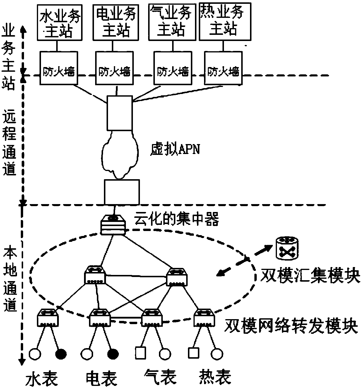
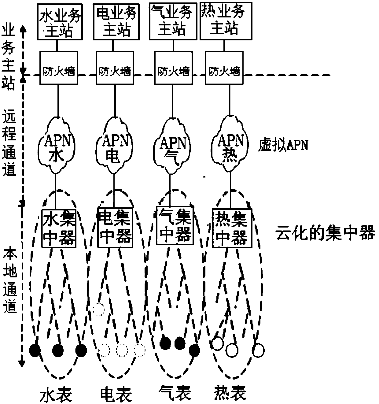
[0031] This embodiment provides a multi-table centralized copying system, which is a 4-table centralized copying system, such as figure 1 It is a physical topology diagram, and Figure 2 is a logical schematic diagram, including electric meters, water meters, gas meters and heat meters. The measurement control layer is used for instrument information measurement and control, and the system management layer, remote channel layer, data acquisition layer and local communication layer form 4 virtual networks; the 4 virtual networks are decoupled from logical control and physical resources The method is formed by virtualizing one physical network, and the remote channel layer and the data acquisition layer in the four virtual networks are physically multiplexed; the one physical network includes one business master station, one remote channel network, one Physical concentrator, 1 network forwarding device.

[0032] The remote channel layer adopts public network or private network. ...

Embodiment 2

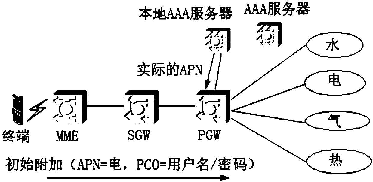
[0046] On the basis of Embodiment 1, this embodiment further proposes the virtualization of the four-meter centralized copying communication network in combination with remote virtual APN (Access PointName) and local SDN (Software Defined Network, software-defined network) virtual network technology Program. In this solution, the power company signs a physical APN channel on the remote channel, and configures four virtual APN channels to connect to the main station of water, electricity, gas, and heat business respectively. Since different uplink channels are logically independent, each business master station can realize real-time control of the acquisition terminal under the condition of sharing the remote channel resources provided by the power company. In the data collection and local communication layer, SDN and cloud technology are used to support the cloudization of local virtual communication network and concentrator. The virtualized local network shares the same phys...

Embodiment 3

[0074] In this embodiment, on the basis of Embodiment 1, the concentrator follows the four independent concentrators in the hard isolation solution. The four physical concentrators correspond to the four uplink virtual APN channels and downlink SDN virtual network respectively.


PUM


Abstract

The invention relates to a multimeter reading system which solves problems about business unsegregated and failure in remote channel multiplexing. The technical scheme includes that n virtual networksare formed by adopting a system management layer, a remote channel layer, a data acquisition layer and a local communication layer; the n virtual networks are virtualized by m physical networks according to a logical control and physical resource decoupling method, the remote channel and the data acquisition layer in the m virtual networks are multiplexed, and a local channel physical channel isa mixed network adopting a broadband carrier and micro-power wireless communication technology; one physical network includes on business master station, one remote channel network, one physical concentrator and one network forwarding equipment and is applicable to the multimeter reading system.

Description

technical field [0001] The invention relates to the field of instrument automatic control, in particular to a multi-meter centralized reading system. Background technique [0002] The management models of municipal public utilities represented by water, electricity, gas and heat have been self-contained for a long time. Although the automatic meter reading systems of these industries have many similarities in communication network structure and business form, because of industry management Due to technical and technical issues, transmission channels and business resource sharing cannot be formed. Except for the automatic meter reading in the power industry, which has the advantages of wide coverage and perfect functions due to the use of modern electric energy collection and monitoring management systems, the automatic meter reading in other industries has the problems of low level and small area coverage. The construction of smart cities has promoted the integration of aut...

Claims


Application Information

Patent Timeline
Patent Type & Authority Applications(China)
IPC IPC(8): G08C17/02G08C19/00H04B3/54H04L12/46
CPCG08C17/02G08C19/00H04B3/54H04L12/4641
Inventor 胡书恺
Owner 胡书恺
Why Eureka
Try Eureka