Power battery as well as power battery cover plate and manufacturing method thereof

A technology of power battery and manufacturing method, which is applied in the direction of battery cover/end cover, battery, battery pack parts, etc., can solve problems such as rubber corrosion, battery leakage, and complicated process, and achieve the goal of ensuring reliability and structural strength Effect

Inactive Publication Date: 2018-02-02
SHENZHEN EVERWIN PRECISION TECH
View PDF3 Cites 8 Cited by
  • Summary
  • Abstract
  • Description
  • Claims
  • Application Information

AI Technical Summary

Problems solved by technology

[0004] The cover plate of a general lithium-ion power battery is composed of a cover body, an insulating sheet, a conductive column, etc., and is usually sealed by riveting or a spring structure, and rubber is used as a sealing insulating material between the cover body and the conductive column. Liquid and other strong corrosive liquids, rubber is prone to corrosion, aging, deformation, etc., resulting in battery leakage and safety problems
The cover plate assembly of the existing power battery is mostly sealed by riveting or retaining spring structure, the process is complicated, the cost is high, and the structural strength is not high, which may easily lead to problems in the reliability of the power battery

Method used


Image

  • Power battery as well as power battery cover plate and manufacturing method thereof
  • Power battery as well as power battery cover plate and manufacturing method thereof

Examples


Embodiment Construction

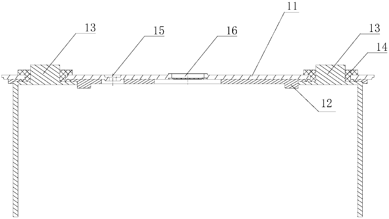
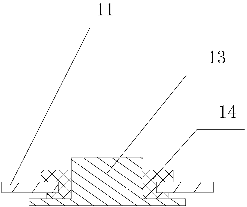
[0015] In one embodiment, such as figure 1 and figure 2 As shown, the power battery cover plate of this embodiment includes a cover plate body 11, an insulating protective layer 12 covering the inner layer of the cover plate body 11, a pole 13 provided through the cover plate body 11, and the pole pole 13 and the cover plate body 11 are formed with an injection molding layer 14 for realizing a sealed connection between the two, a liquid injection hole 15 provided through the cover plate body 11 and used for injecting electrolyte, and a liquid injection hole 15 provided in the cover plate body 11. The explosion-proof device 16 on the plate body 11 is used to discharge the gas inside the battery to release the pressure when the internal pressure of the power battery is high.

[0016] It should be noted that the injection molding layer 14 and the pole post 13 are molded by injection molding and form a chemical bond connection. Furthermore, the cover plate body 11 and the inject...


PUM


Abstract

The application relates to a power battery as well as a power battery cover plate and a manufacturing method thereof. The power battery cover plate comprises a cover plate body, an insulation protective layer covered on an inner layer of the cover plate body, and a post terminal penetrating through the cover plate body, wherein an injection molding layer for realizing a sealed connection between the post terminal and the cover plate body is arranged between the post terminal and the cover plate body, and the injection molding layer and the post terminal are molded through an injection moldingmode and form a chemical bond connection. According to the application, a chemically bonded injection molding layer is molded and formed on the surface of the post terminal by adopting an injection molding mode, the sealed connection between the post terminal and the cover plate body can be achieved by using the injection molding layer, and thus the problems of complex process, higher cost, low structural strength, lower reliability of the power battery and the like caused by adopting a riveting or snap spring structure for sealing in the prior art can be effectively avoided; and according tothe application, the complexity of a manufacturing process can be reduced through the injection molding mode, a low cost can be achieved, and the structural strength and the equipment reliability canbe ensured.

Description

technical field [0001] The invention relates to the technical field of power battery components, in particular to a power battery, a power battery cover plate and a manufacturing method thereof. Background technique [0002] Lithium batteries are widely used in various industries, such as 3C electronics, new energy vehicles, etc. However, due to their own characteristics, lithium batteries have great safety problems, such as fire and explosion. Especially in the field of electric vehicles, it is related to the safety of the vehicle and the safety of personnel. As the core component of the battery assembly, the power battery cover has a great impact on the normal use of the vehicle. [0003] Lithium-ion power batteries are the key components of new energy energy output, and they account for a relatively high proportion of the overall cost of new energy vehicles. This also leads to the lack of competitiveness of new energy vehicles compared with traditional vehicles. Therefore...

Claims


Application Information

Patent Timeline
Patent Type & Authority Applications(China)
IPC IPC(8): H01M2/08H01M2/04H01M2/06B29C45/14C08L23/12C08L51/06B29L31/34H01M50/147H01M50/172H01M50/183
CPCC08L23/12B29C45/14467B29C2045/14868B29L2031/3468H01M2220/20C08L2203/20H01M50/147H01M50/183H01M50/172C08L51/06Y02E60/10
Inventor 曾志亮
Owner SHENZHEN EVERWIN PRECISION TECH
Why Eureka
Try Eureka