Eureka AIR delivers breakthrough ideas for toughest innovation challenges, trusted by R&D personnel around the world.

A cascading submicrosecond-level high voltage pulse generator for vacuum arc-extinguishing chamber aging

A vacuum interrupter, high-voltage pulse technology, applied in electric pulse generator circuits, energy storage elements to generate pulses, and conversion equipment without intermediate conversion to AC, which can solve the impact, increase the cost of primary devices, and affect pulse generation. It can improve the working efficiency of the output pulse front index and other issues, so as to achieve the effect of increasing the amplitude, reducing the working current and working voltage, and satisfying the high repetition rate and long-life operation.

Inactive Publication Date: 2018-02-02
XI AN JIAOTONG UNIV +2
View PDF7 Cites 2 Cited by
  • Summary
  • Abstract
  • Description
  • Claims
  • Application Information

AI Technical Summary

Problems solved by technology

[0003] For the design of the above pulse power supply, it is not a small challenge to meet the high output voltage amplitude and faster pulse rising edge index at the same time, because a higher pulse amplitude means a larger transformer winding scale and insulation volume overhead, As a result, the increase in transformer primary and secondary flux leakage and winding parasitic parameters will directly affect the working efficiency of the pulse generator and the leading edge index of the output pulse; and if you choose to reduce the winding ratio to improve the waveform index, it means It is necessary to increase the working voltage of the primary side of the transformer, which will increase the cost of the primary side devices, especially affecting the core components of the pulse power technology, the selection of the control conduction switch

Method used


Image

  • A cascading submicrosecond-level high voltage pulse generator for vacuum arc-extinguishing chamber aging
  • A cascading submicrosecond-level high voltage pulse generator for vacuum arc-extinguishing chamber aging

Examples


Embodiment Construction

[0014] The present invention is described in further detail below in conjunction with accompanying drawing:

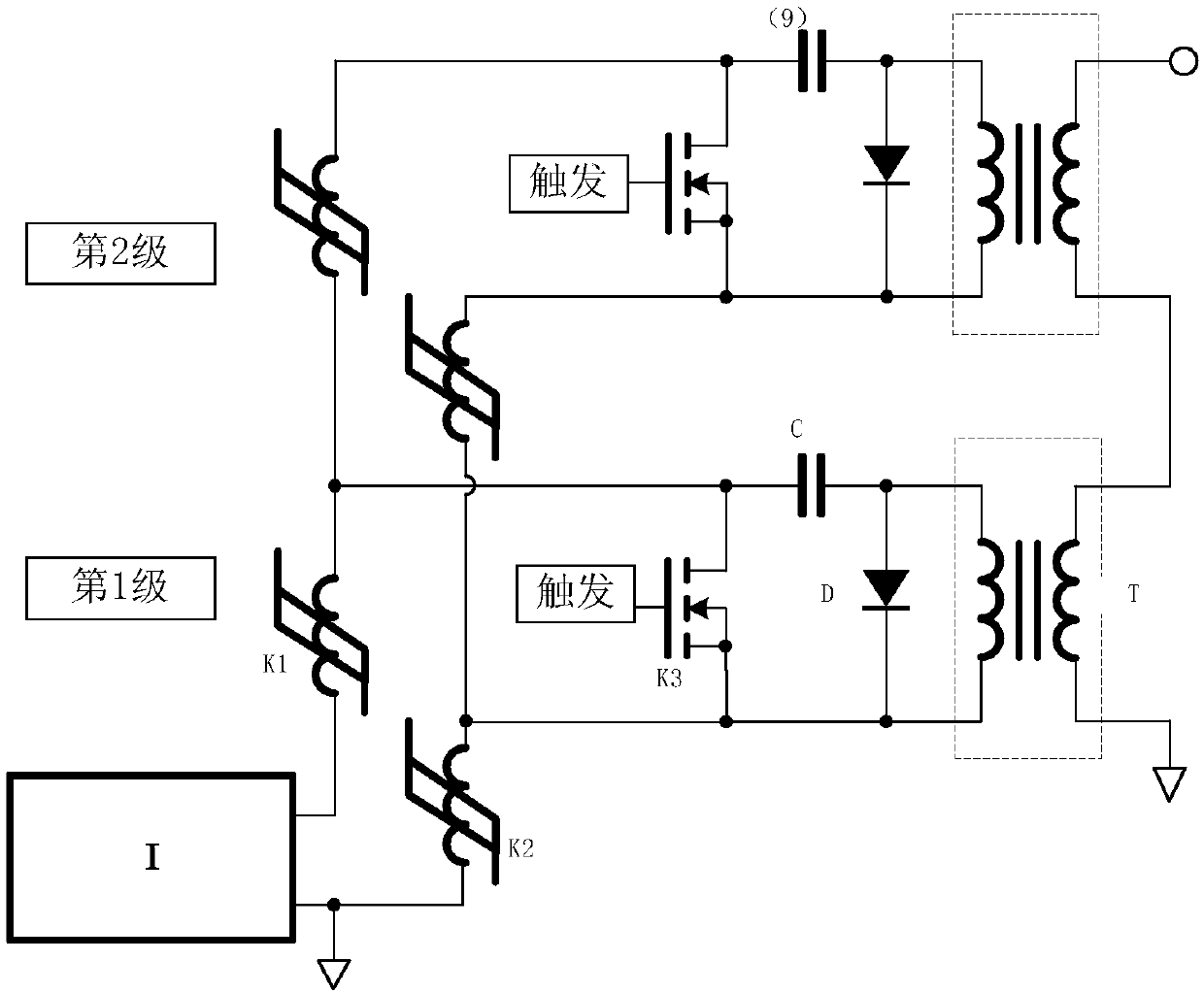
[0015] The cascaded sub-microsecond high-voltage pulse generator used for vacuum interrupter burn-in according to the present invention includes a DC charging power supply I and several pulse transformer assemblies, wherein each pulse transformer assembly includes a pulse transformer T, a freewheeling Diode D, energy storage capacitor C, control switch K3, first magnetic switch K1 and second magnetic switch K2, wherein one end of the primary winding of the pulse transformer T is connected to the anode of the freewheeling diode D and one end of the energy storage capacitor C , the other end of the energy storage capacitor C is connected to one end of the control switch K3 and one end of the first magnetic switch K1, one end of the second magnetic switch K2 is connected to the negative pole of the freewheeling diode D, the other end of the control switch K3 and the pulse ...


PUM


Abstract

The invention provides a cascading submicrosecond-level high voltage pulse generator for vacuum arc-extinguishing chamber aging. For each pulse transformer component, one end of a primary side windingof a pulse transformer is connected with the positive electrode of a flywheel diode and one end of an energy storage capacitor; the other end of the energy storage capacitor is connected with one endof a control switch and one end of a first magnetic switch; one end of a second magnetic switch is connected with the negative electrode of the flywheel diode, the other end of the control switch andthe other end of the primary side winding of the pulse transformer. The other end of the first magnetic switch in a previous pulse transformer component is connected with a line between the first magnetic switch and the energy storage capacitor of the next pulse transformer component; secondary side windings of pulse transformers in the pulse transformer components are connected in series. The amplitude of pulse voltage output by the pulse transformer is relatively high and the cost is relatively low.

Description

technical field [0001] The invention belongs to the technical field of pulse power, and relates to a cascaded submicrosecond high-voltage pulse generator used for aging of vacuum interrupters. Background technique [0002] As an important link in the production process of vacuum interrupters, aging has been widely used in the field of electric vacuum. For pulse aging technology, according to the literature (Xiaoshe Zhai, Wei Zhang, Xiaofei Yao, Distribution of High-Voltage and High Frequency Impulse Breakdown Sparks in ConitionedContact Surface[C], in proceedings of the 27th ISDEIV, Suzhou, China, pp 33-36.2016.Sep), based on the research results of the fast frontier narrow pulse aging (usually sub-microsecond level), due to the single The secondary breakdown energy is limited and controllable, thus suppressing the de-aging process of the contact, that is, each pulse breakdown can always be located at the weak point area of ​​the insulation on the contact surface, avoiding t...

Claims


Application Information

Patent Timeline
IPC IPC(8): H02M9/04H02M3/07
CPCH03K3/53H02M3/07
Inventor 刘畅翟小社李仁峰李小钊薛从军侯小默葛媛媛张伟
Owner XI AN JIAOTONG UNIV
Why Eureka
Eureka Blog
Learn More