Intelligent waste gas treatment system for optical fiber preform production equipment

A technology for optical fiber preforms and production equipment, applied in the field of optical fiber equipment, can solve problems such as energy consumption, prolong processing time, and lose waste gas energy, and achieve the effects of maintaining neutralization and absorption capacity, realizing rational utilization, and improving practicability.

Inactive Publication Date: 2018-02-09
SHENZHEN BEIYOUTONG NEW ENERGY TECH DEV CO LTD
View PDF6 Cites 2 Cited by
  • Summary
  • Abstract
  • Description
  • Claims
  • Application Information

AI Technical Summary

Problems solved by technology

[0003] Most of the existing waste gas treatment equipment uses spray towers to remove dust and absorb acid gas from the waste gas produced by optical fiber preforms. However, during the treatment process, due to the high temperature of the waste gas, the energy of the waste gas will be lost by spraying to cool down. It is impossible to make reasonable use of its thermal energy. Not only that, the acid gas absorbed by spraying is very limited. In order to ensure the absorption effect, it is necessary to carry out multiple reflux absorption, which not only prolongs the processing time, but also consumes a lot of energy and wastes Energy, which in turn reduces the availability of existing waste gas treatment equipment

Method used


Image

  • Intelligent waste gas treatment system for optical fiber preform production equipment
  • Intelligent waste gas treatment system for optical fiber preform production equipment
  • Intelligent waste gas treatment system for optical fiber preform production equipment

Examples


Embodiment Construction

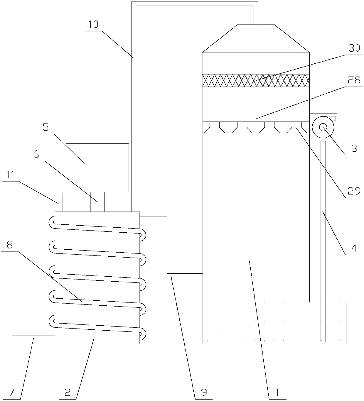
[0028] The present invention is described in further detail now in conjunction with accompanying drawing. These drawings are all simplified schematic diagrams, which only illustrate the basic structure of the present invention in a schematic manner, so they only show the configurations related to the present invention.

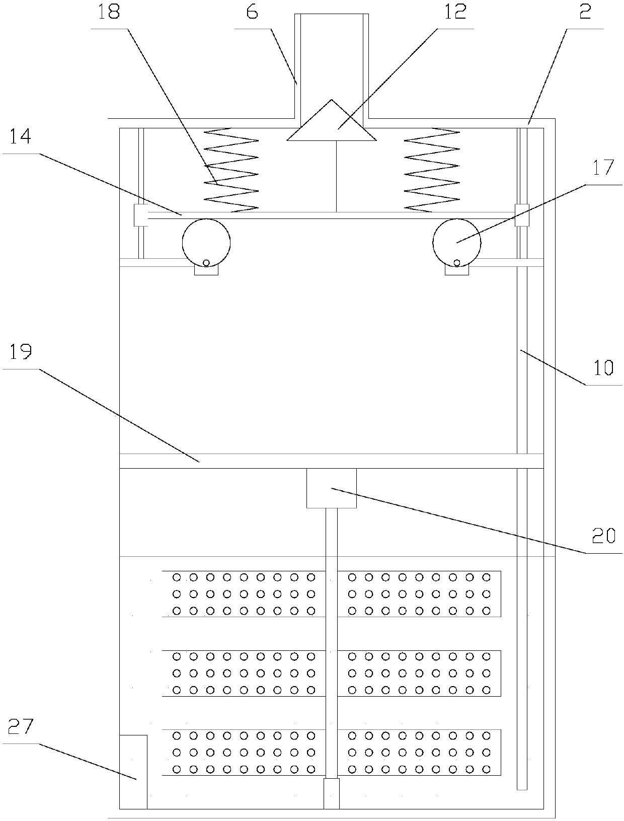
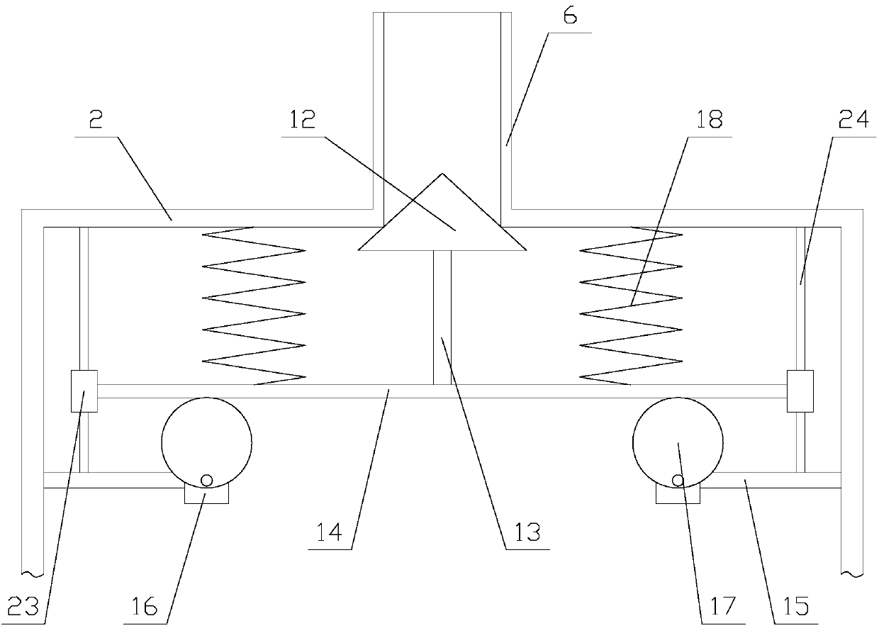
[0029] like Figure 1-Figure 4 As shown, an intelligent waste gas treatment system for optical fiber preform production equipment includes a spray tower 1, a reaction chamber 2, a pipeline mechanism, a water pump 3, a first water pipe 4, a feeding chamber 5 and a feeding pipe 6, the The spray tower 1 is arranged on one side of the reaction chamber 2, the water pump 3 is fixed on the spray tower 1, the bottom end of the first water pipe 4 is arranged at the bottom of the spray tower 1, and the first water pipe 4 The top of the top is communicated with water pump 3, and described feed chamber 5 is fixed on the top of reaction chamber 2 by feed pipe 6, and descr...


PUM


Abstract

The invention relates to an intelligent waste gas treatment system for optical fiber preform production equipment. The system comprises a spray tower, a reaction chamber, a pipeline mechanism, a waterpump, a first water pipe, a feeding chamber and a feeding pipe, wherein the reaction chamber is internally provided with a feeding mechanism and a mixing mechanism, the feeding mechanism comprises ablock, a vertical bar, a transverse board and two feeding units, and the mixing mechanism comprises a transverse bar, a second motor, a second driving shaft and two mixing units. According to the intelligent waste gas treatment system for optical fiber preform production equipment, the outer wall of the reaction chamber absorbs the heat of the waste gas through a wound pipe, so that a reaction liquid and the waste gas are neutralized at a faster speed, waste gas heat is used reasonably, and the neutralizing reaction is carried out completely due to the mixing mechanism, further, the feeding mechanism allows an alkaline agent in the feeding chamber to enter the reaction chamber from the feeding pipe, and the alkaline agent is dissolved in the reaction liquid, so that the reaction liquid recovers alkaline so as to keep neutralizing and absorbing acidic waste gas, and the system is more practical.

Description

technical field [0001] The invention relates to the field of optical fiber equipment, in particular to an intelligent waste gas treatment system for optical fiber preform production equipment. Background technique [0002] During the production of optical fiber preform rods, a large amount of waste gas containing hydrogen chloride and silica dust will be generated, which must be treated to meet national and local standards before being discharged. The characteristics of the waste gas produced by light rods: the silica dust particles produced are small, with a particle size of about 5 to 10 microns, and the amount of dust is large; it is highly corrosive, and the waste gas contains hydrogen chloride and chlorine; the temperature of the waste gas discharged from the equipment is high (above 250 °C ). [0003] Most of the existing waste gas treatment equipment uses spray towers to remove dust and absorb acid gas from the waste gas produced by optical fiber preforms. However, d...

Claims


Application Information

Patent Timeline
IPC IPC(8): B01D47/06B01D53/78B01D53/68
CPCB01D47/06B01D53/68B01D53/78
Inventor 蒙泽喜
Owner SHENZHEN BEIYOUTONG NEW ENERGY TECH DEV CO LTD
Why Eureka
Try Eureka