Cleaning device for cleaning oil bucket

A cleaning device and a technology for cleaning oil, which are applied in the directions of cleaning methods using liquids, cleaning hollow objects, cleaning methods and utensils, etc., can solve the problems of disproportion between input and output, strong viscosity of oil, and low cleaning efficiency, etc. To achieve the effect of fast cleaning, simple cleaning process and clean cleaning

Inactive Publication Date: 2018-02-09
CHENGDU YUELUN TRADING CO LTD
View PDF0 Cites 0 Cited by
  • Summary
  • Abstract
  • Description
  • Claims
  • Application Information

AI Technical Summary

Problems solved by technology

[0003] The advent of the industrial age has increased people's demand for oil. Most of the oil transportation is made of iron sheets. With the development of my country's economy, tens of millions of oil barrels are scrapped every year in our country. In order to save resources, oil barrels Cleaning and reusing, there is a large amount of oil in the oil barrel of the exhaust gas, which is very easy to ignite, and the oil is very viscous, which is very difficult to clean. The manual cleaning method is time-consuming and laborious, and the cleaning efficiency is low. Out of proportion, so many oil barrels are directly scrapped, resulting in a serious waste of resources

Method used


Image

  • Cleaning device for cleaning oil bucket
  • Cleaning device for cleaning oil bucket

Examples


Embodiment 1

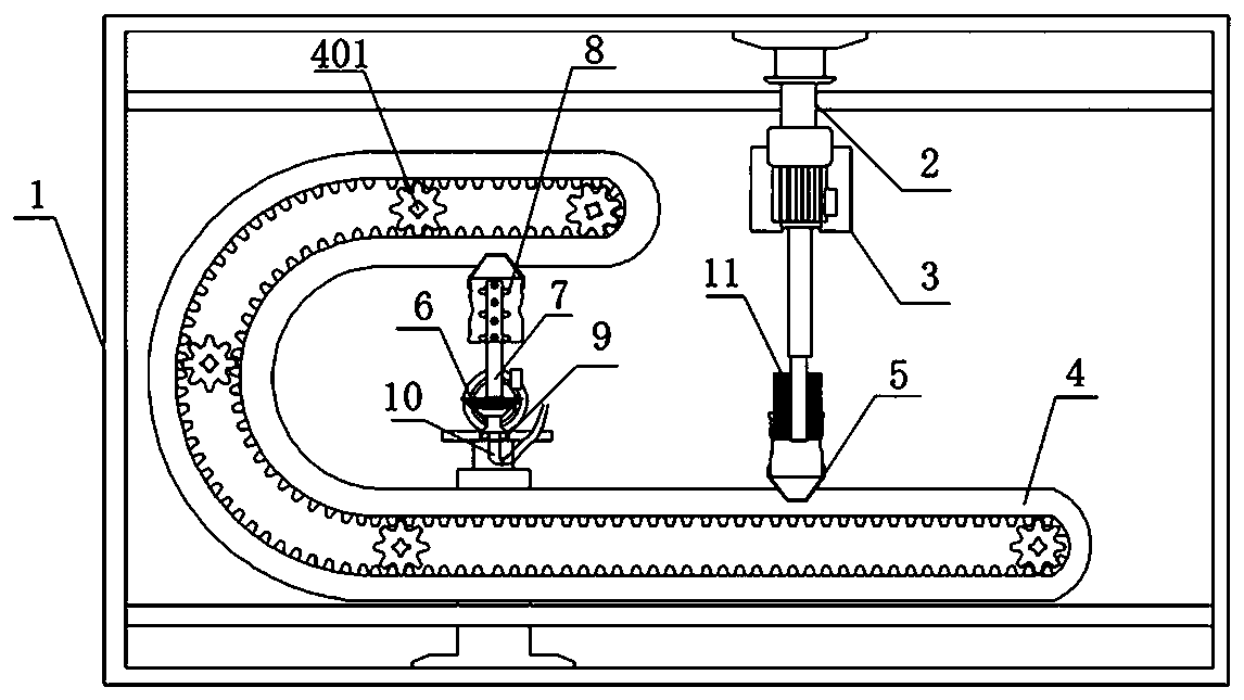
[0027] combined with figure 1 , figure 2 As shown, a cleaning device for cleaning oil barrels includes a support frame 1, an A hydraulic cylinder 2 is installed on the top of the support frame 1, and a cleaning motor 3 is fixed on the top of the A hydraulic cylinder 2. The cleaning The top of the motor 3 is provided with a brush 11;

[0028] A transmission belt 4 is fixed inside the support frame 1, and a fixing seat 5 for fixing an oil drum is installed on the transmission belt 4. The angle of inflection is in degrees;

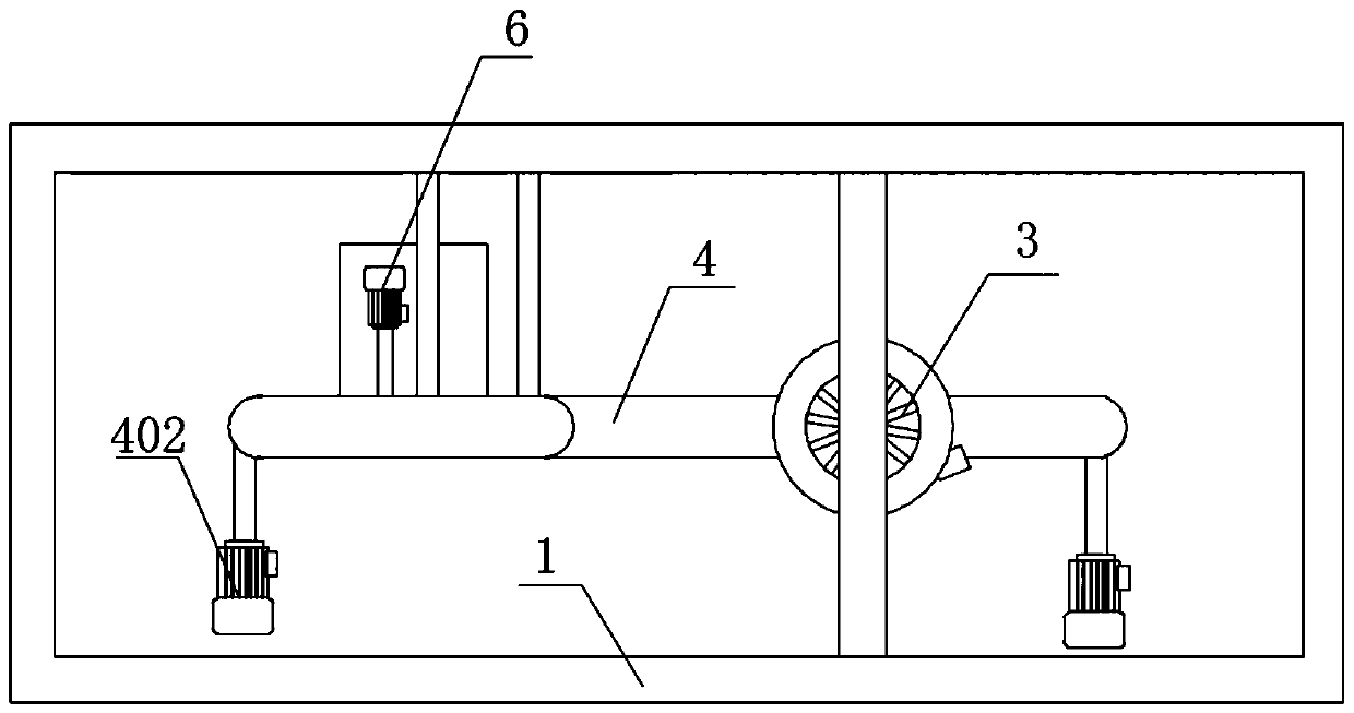
[0029] The bottom of the support frame 1 is provided with a lifting device close to the arc-shaped bending end of the transmission belt 4, and the lifting device is provided with a rotating motor 6, and the rotating motor 6 is connected to a water spray pipe 7 through a gear transmission assembly. Spray nozzles 8 are arranged on the top and sides of the water spray pipe 7 , and a bearing 9 is sealedly connected to the bottom end of the water spray pipe 7 ...

Embodiment 2

[0033] In order to improve the stability of the cleaning device, on the basis of the structure and principle of the embodiment, the attached figure 1 , attached figure 2 As shown, in this embodiment, the hydraulic cylinder is welded on the support frame 1, the brush 11 is arranged on the top of the fixing seat 5, and the inside of the transmission belt 4 is provided with a transmission gear 401, and the transmission gear 401 drives A transmission motor 402 is connected.

[0034] Structural principles:

[0035] The hydraulic cylinder is welded on the support frame 1. The welded structure has high strength and stability. The hydraulic cylinder is connected to the cleaning motor 3 and is clamped or riveted. It is easy to loosen the riveting point during long-term vibration, which will cause accidents and affect the service life. A transmission gear 401 is arranged inside, and the transmission gear 401 is connected to the transmission motor 402 to drive the transmission belt 4 ...

Embodiment 3

[0037] In order to improve the cleaning effect and adapt the cleaning device to oil drums of different specifications, on the basis of the structure and principle of the embodiment, further combine the attached figure 1 , attached figure 2 As shown, the lifting device in this embodiment is a B hydraulic cylinder, and the inner side of the fixed seat 5 is provided with anti-slip lines, the material of which is rubber, and the brush 11 is screwed to the rotating shaft of the cleaning motor 3, so that The above-mentioned gear transmission assembly is two bevel gears whose axes are perpendicular to each other and mesh with each other.

[0038] Structural principles:

[0039] In order to increase the lifting speed of the water spray pipe 7 and simplify the lifting structure, the lifting device is a B hydraulic cylinder. The lifting structure of the hydraulic cylinder is simple and practical. The side wall inside the 5 is provided with rubber anti-slip lines. When the oil drum is p...


PUM


Abstract

The invention discloses a cleaning device for cleaning oil barrels, which comprises a support frame, a hydraulic cylinder A is installed on the top of the support frame, a cleaning motor is fixed on the top of the hydraulic cylinder A, and a cleaning motor is installed on the top of the cleaning motor. There are brushes; a transmission belt is fixed inside the support frame, and a fixing seat for fixing the oil drum is installed on the transmission belt. The angle is in degrees: the bottom of the support frame is provided with a lifting device close to the arc-shaped bending end of the transmission belt, and the lifting device is provided with a rotating motor, and the rotating motor is connected to a water spray pipe through a gear transmission assembly. Spray nozzles are arranged on the top and side of the water spray pipe, and the bottom end of the water spray pipe is sealed and connected with a bearing, and the bearing is rotatably connected with a water delivery pipe.

Description

technical field [0001] The invention relates to the field of cleaning and processing of oil drums, in particular to a cleaning device for oil drums. Background technique [0002] Petroleum, one of the main objects of geological exploration, is a viscous, dark brown liquid that originally became the blood of industry. There are petroleum reserves in some areas of the upper crust. Petroleum is mainly composed of hydrocarbons. Colored, flammable, oily liquid with a characteristic odour. Strictly speaking, petroleum is mainly composed of hydrocarbons composed of hydrogen and carbon. The chemicals that make up petroleum can be broken down by distillation. As processed products, crude oil includes kerosene, benzene, gasoline, paraffin, asphalt, etc. Strictly speaking, petroleum is mainly composed of hydrocarbons composed of hydrogen and carbon. The four hydrocarbons with the smallest molecular weight are all gas. The color of crude oil is very rich, ranging from very red, gold...

Claims


Application Information

Patent Timeline
Patent Type & Authority Applications(China)
IPC IPC(8): B08B9/36B08B9/30B08B3/10
CPCB08B9/36B08B3/10B08B9/30
Inventor 李云娟
Owner CHENGDU YUELUN TRADING CO LTD
Why Eureka
Try Eureka