
Herringbone hanging bracket disassembling method

A herringbone and hanger technology, applied in the direction of load hanging components, cranes, hoisting devices, etc., can solve the problems of low utilization rate, achieve the effect of small impact, reduce resistance, and protect the bottom of the strut

Inactive Publication Date: 2018-02-09
李忠华
View PDF0 Cites 2 Cited by
  • Summary
  • Abstract
  • Description
  • Claims
  • Application Information

AI Technical Summary

Problems solved by technology

[0005] Aiming at the problem that the structural design of the hanger used to build on the top floor of the building in the prior art proposed above makes its utilization rate low, the present invention provides a method for decomposing the herringbone hanger, which can be used to realize the hanger demolition and separation

Method used


Image

  • Herringbone hanging bracket disassembling method
  • Herringbone hanging bracket disassembling method

Examples


Embodiment 1

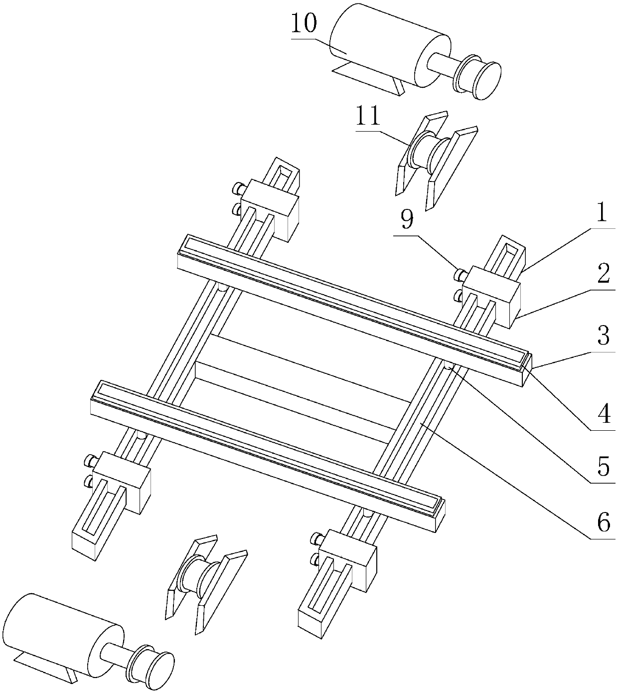
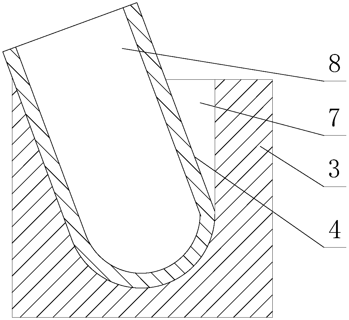
[0038] Such as figure 1 and figure 2 As shown, a method for decomposing a herringbone hanger, the method uses the following device to realize the decomposition of a herringbone hanger, and the form of the hanger is that the legs of the hanger are a multi-section combined structure, and each rod forming the legs The connection form between the segments is a detachable connection form: the device includes two mutually parallel turning tanks 4, and each turning tank 4 is provided with a strip-shaped second and parallel to the length direction of the turning tank 4. Groove 8, the opening end of the second groove 8 faces upward;

[0039] It also includes two hoisting machines 10, and two turning tanks 4 are located between the two hoisting machines 10;

[0040] The implementation steps of the decomposition method are:

[0041] S1. Fix two stay ropes on the top of the hanger, and the above two stay ropes are respectively wound on different winches 10;

[0042] S2. The hanger is...

Embodiment 2

[0047] Such as figure 1 and figure 2 As shown, the present embodiment is further limited on the basis of Embodiment 1: it also includes strip-shaped turning seats 3, the number of said turning seats 3 is two, and the turning seats 3 are parallel to each other, and each turning seat 3 are provided with a first groove 7 parallel to the length direction of the flip seat 3, and the opening ends of the first groove 7 are all upward;

[0048] Two turning grooves 4 are respectively installed in different first grooves 7, the turning grooves 4 are parallel to the turning seat 3, and the width of the opening end of each first groove 7 is greater than the width of the inner turning groove 4 , the bottom of each first groove 7 is in contact with the bottom of the inner turning tank 4, and each turning tank 4 can swing in the corresponding first groove 7 with its own bottom as the center of rotation. Since the turning tank body 4 can swing in the first groove 7, the turning tank body 4...


PUM


Abstract

The invention discloses a decomposing method for a herringbone hanger. The realization of the decomposing method depends on the following device: the device comprises two mutually parallel inversion groove bodies, and each inversion groove body is provided with a strip shape and is connected with the inversion groove. A second groove parallel to the length direction of the body, and the open end of the second groove is upward; it also includes two hoists, and the two inverting groove bodies are located between the two hoists; the method is used for a herringbone hanger and the outriggers of the hanger are multi-segment combined structures, and the connection relationship between the rod segments constituting the outriggers is a detachable connection relationship. The method can be used to realize the dismantling and separation of the hanger.

Description

technical field [0001] The invention relates to the technical field of building construction hoisting equipment, in particular to a method for decomposing a herringbone hanger. Background technique [0002] With the advancement of science and technology, more and more high-rise buildings are being constructed in the process of building construction. As an important construction tool, hoisting equipment plays a pivotal role in the construction of high-rise buildings. [0003] For high-rise twin-tower buildings, the traditional vertical tower cranes are difficult to build and dismantle. In the prior art, the built buildings are also used as the base, and the herringbone or door-shaped hangers will be erected on the top floor of the building. The hanger can be directly used as a hoisting tool for building materials and construction equipment. When the tower crane is dismantled, the hanger built on the top floor of the building is also used as a release tool for the tower crane ...

Claims


Application Information

Patent Timeline
Patent Type & Authority Applications(China)
IPC IPC(8): B66C13/00B66C13/04B66D1/60B66C23/00
CPCB66C13/00B66C13/04B66C23/00B66D1/60
Inventor 李忠华
Owner 李忠华
Learn More