Disc film dehumidifier and dehumidifying system

A dehumidifier and disc type technology, applied in the field of disc type membrane dehumidifier and dehumidification system, can solve the problems of pipeline and equipment corrosion, reduce heat exchange efficiency, air entrainment of hygroscopic agent, etc., to avoid corrosion, enhance disturbance, Avoid heat transfer efficiency and hygroscopic effects

Active Publication Date: 2018-02-09
DONGGUAN UNIV OF TECH
View PDF7 Cites 3 Cited by
  • Summary
  • Abstract
  • Description
  • Claims
  • Application Information

AI Technical Summary

Problems solved by technology

Liquid dehumidification and regeneration are easy, but the disadvantage is that the air is in direct contact with the liquid hygroscopic agent, which can easily cause the air to entrain the hygroscopic agent, further causing corrosion of pipelines and equipment
In addition, as the heating progresses, the temperature of the solution increases, which will reduce the heat transfer efficiency.

Method used


Image

  • Disc film dehumidifier and dehumidifying system
  • Disc film dehumidifier and dehumidifying system
  • Disc film dehumidifier and dehumidifying system

Examples


Embodiment 1

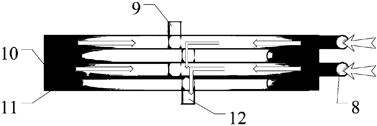
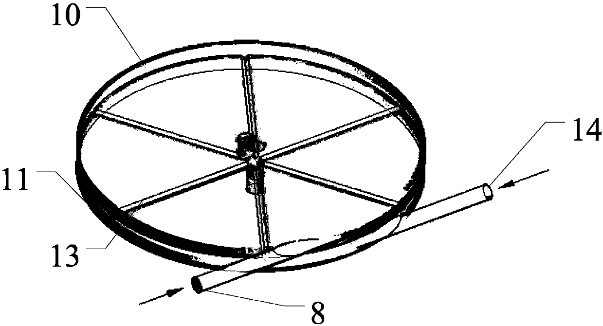
[0049] Such as figure 2 ,with image 3 As shown, the disc membrane dehumidifier is composed of multiple solution channels and air channels alternately arranged and combined. Two adjacent channels are separated by a semi-permeable membrane, and a solution channel 10 and an air flow A unit composed of channel 11 will be explained. When dehumidifying, the dehumidifying solution enters the solution flow channel 10 from the liquid inlet 8, and the dehumidifying solution flows in a vortex counterclockwise direction in the flow channel, and finally flows out of the flow channel at the center of the flow channel. Then it flows through the next solution flow channel or flows out of the disc membrane dehumidifier from the liquid outlet 12; at the same time, the outdoor fresh air flows into the air flow channel 11 from the air inlet 14 and the inlet direction of the air inlet 14 is in the direction of the liquid inlet 8 At 180°, the air enters the flow channel and flows clockwise in a vor...

Embodiment 2

[0054] The main technical solution in this embodiment is the same as that in Embodiment 1. For the features that are not explained in this embodiment, the explanation in Embodiment 1 is adopted, which will not be repeated here. Such as Figure 5 As shown, the difference between this embodiment and the first embodiment is that a coil-type cooling tube 15 is installed in each solution flow channel 10.

[0055] When working, the dehumidifying solution absorbs water vapor in the air, and the latent heat of water vapor causes the temperature of the dehumidifying solution to rise and the dehumidification efficiency to decrease. Therefore, when the dehumidifier is working, cooling water or cooling is passed into the coiled cooling pipe 15 at the same time. The gas takes away the dehumidification heat of the dehumidification liquid, which is the dehumidification liquid to restore higher dehumidification efficiency.

Embodiment 3

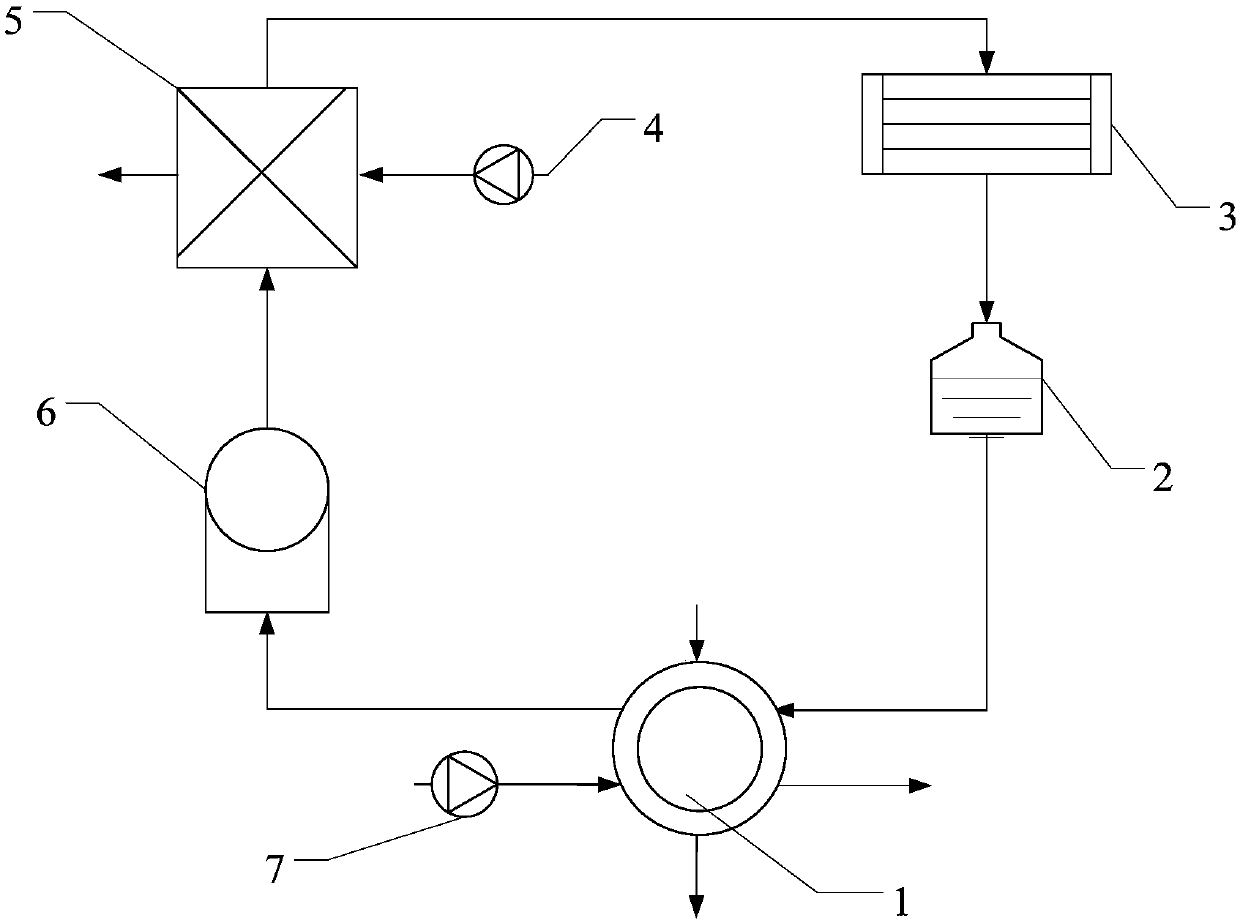
[0057] Such as figure 1 As shown, a dehumidification system includes a disc membrane dehumidifier 1, a liquid storage tank 2, a cooler 3, a second induced draft fan 4, a regenerator 5, a heater 6 (a solar heater is selected), and an induced draft fan 7. . During operation, the concentrated dehumidifying solution in the liquid storage tank 2 flows into the disc membrane dehumidifier 1. The dehumidified dehumidifying solution absorbs water vapor so that the concentration becomes low, and it flows through the heater 6 for heating, which is required for regeneration. After reaching the temperature, it flows into the regenerator 5 for concentration regeneration. The dehumidifying solution after the regenerator 5 is restored to a concentrated solution. At this time, the solution temperature is higher and the dehumidification efficiency is lower. It flows through the cooler 3 for cooling, and finally flows into the liquid storage tank 2 is stored in the dehumidifier 1 again for dehumi...


PUM


Abstract

The invention discloses a disc film dehumidifier and a dehumidifying system. The dehumidifier comprises a shell, an air runner and a solution runner; the shell is disc-shaped; the air runner and the solution runner are both plane spiral pipes, are contacted, and are in parallel; and an included angle of projections of an intake port and a liquid feed port on a horizontal plane is 180 degrees, so that gas entering the air runner and liquid in the solution runner are opposite in flowing direction to form countercurrents or quasi countercurrents. The corresponding dehumidifying system comprises the disc film dehumidifier. The disc film dehumidifier and the dehumidifying system have such advantages as full heat exchange, good mass transfer effect and high moisture absorbing efficiency.

Description

Technical field [0001] The invention belongs to the technical field of air dehumidification, and specifically relates to a disc membrane dehumidifier and a dehumidification system. Background technique [0002] Air humidity is a key factor affecting environmental comfort. In hot and humid climates, especially in Gulf cities, dehumidification is almost as important as cooling. Studies have shown that the suitable relative humidity for the human body is 40-60%. Excessive humidity can cause discomfort to the human body, and in severe cases, it can also cause the proliferation of certain viruses and bacteria inside the building. [0003] With the development of the national economy, people's living standards have been continuously improved, and the requirements for the humid and hot environment of buildings have also been continuously improved. The application of air conditioners has become more and more extensive, and the requirements for air conditioning systems have become higher a...

Claims


Application Information

Patent Timeline
Patent Type & Authority Applications(China)
IPC IPC(8): F24F3/14F24F13/00
CPCF24F3/14F24F13/00F24F2003/144
Inventor 黄斯珉杨敏林陈阳辉胡冰陶实刘鉴
Owner DONGGUAN UNIV OF TECH
Why Eureka
Try Eureka