
Eddy Current Probe Single Axis Pusher

A technology of eddy current probes and pushers, applied in the direction of instruments, scientific instruments, measuring devices, etc., can solve the problems of affecting transmission efficiency and detection effect, troublesome operation, easy to wear probes, etc., to ensure synchronization and timeliness, and not easy Effects of damage, ease of maintenance and maintenance

Active Publication Date: 2021-03-16
CGNPC INSPECTION TECH +3
View PDF6 Cites 1 Cited by
  • Summary
  • Abstract
  • Description
  • Claims
  • Application Information

AI Technical Summary

Problems solved by technology

[0003] Chinese patent 201120161378.1 discloses an eddy current probe pusher, which is mainly composed of a reel frame, a probe signal interface, and a motor shaft. , rack, gear, upper pressing plate and lower pressing plate and other components cooperate to carry out mechanical pressing, but this method is manual pressing, which is troublesome to operate, and in this patent, the probe cable is placed between the pressing wheel and the lower pressing plate. In the semi-circular groove between the driving wheels, the gap between the pinch wheel and the drive wheel is adjusted to adapt to probes of different diameters, but this makes the contact between the probe and the pinch wheel and the drive wheel a rigid contact, not only in the transmission It is easy to wear the probe during the process, and if the diameter of the probe is not uniform enough, the probe will be deformed during the transmission process or squeezed by the pinch wheel and the drive wheel, or there will be a gap between the pinch wheel and the drive wheel and not enough The static friction required for the transmission, thus affecting the transmission efficiency and detection effect

Method used


Image

  • Eddy Current Probe Single Axis Pusher
  • Eddy Current Probe Single Axis Pusher
  • Eddy Current Probe Single Axis Pusher

Examples


Embodiment Construction

[0029] The present invention will be further described below in conjunction with the accompanying drawings and embodiments.

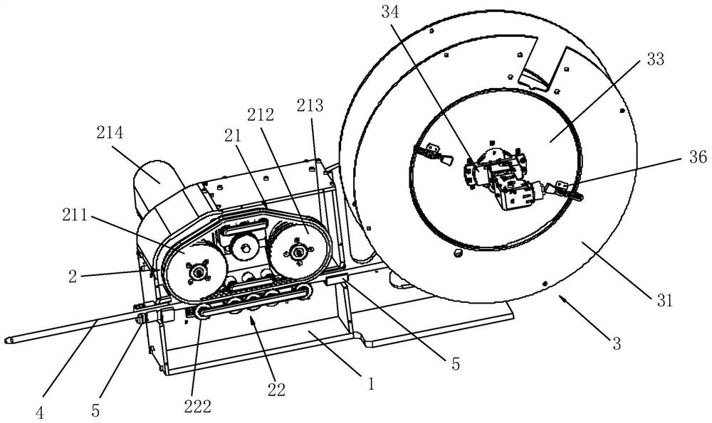
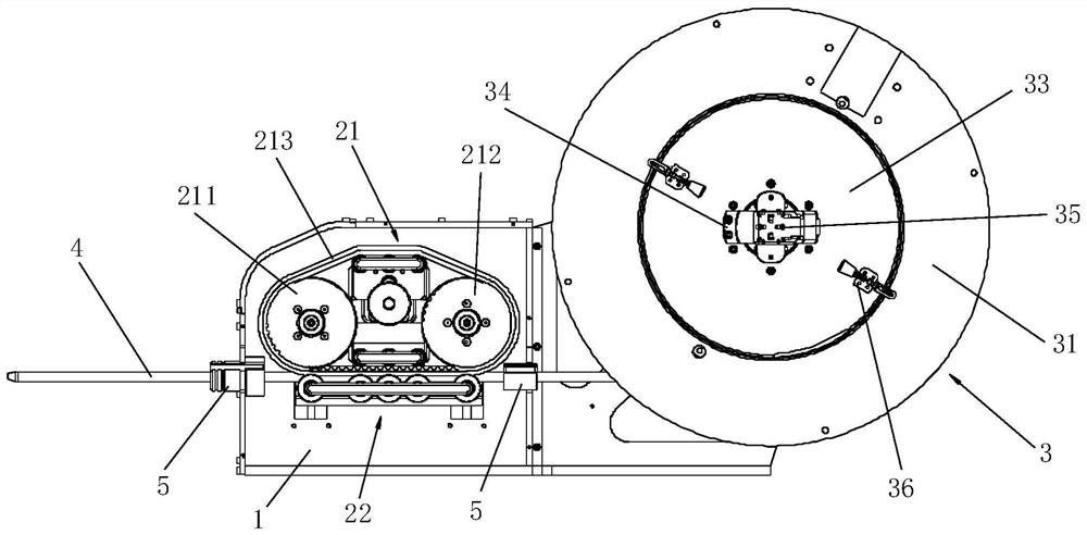
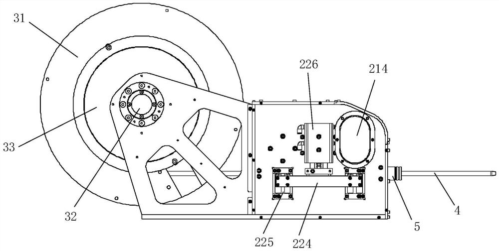
[0030] like Figure 1 to Figure 3 As shown, an eddy current probe single-axis pusher is suitable for a coilable cable-like probe 4, the pusher includes a mounting frame 1, and is arranged on the mounting frame 1 for winding and releasing the winding of the probe 4. The device 3, the probe 4 has a release section protruding from the winding device 3, the pusher also includes a delivery device 2 arranged on the mounting frame 1 for clamping the release section, the delivery device 2 includes a delivery device arranged on the installation frame 1 The belt pulley assembly 21 and the C-shaped pressing wheel assembly 22 that can move up and down on the mounting frame 1 and opposite to the belt pulley assembly 21, there is a gap between the belt pulley assembly 21 and the C-shaped pressing wheel assembly 22 to accommodate the probe 4 And a transmission channe...


PUM


Abstract

The invention relates to the technical field of nondestructive testing devices, in particular to a vortex probe single-shaft push-puller. The push-puller comprises an installing rack and a winding device arranged on the installing rack and used for winding and releasing a probe, wherein the probe is provided with a release section extending out of the winding device. The push-puller also comprisesa conveying device arranged on the installing rack and used for clamping the release section, wherein the conveying device comprises a belt wheel assembly arranged on the installing rack and a C-shaped compressing wheel assembly capable of vertically moving, arranged on the installing rack and arranged opposite to the belt wheel assembly, wherein a conveying channel for containing the probe to make the probe pass through in its length direction is arranged between the belt wheel assembly and the C-shaped compressing wheel assembly, and the winding device comprises a probe plate rotatably arranged on the installing rack and used for winding the probe. The vortex probe single-shaft push-puller is simple in structure, light and capable of achieving automatic pushing and pulling in the vortexdetecting process.

Description

technical field [0001] The invention relates to the technical field of non-destructive testing equipment, in particular to a single-axis pusher for an eddy current probe. Background technique [0002] Eddy current testing is a non-destructive testing technology widely used in the defect inspection of heat transfer tubes in heat exchangers. It has high sensitivity to the defects of the inner and outer walls of the tube, and can detect defects in time and accurately, which is an important guarantee for the safe operation of equipment. When performing eddy current testing on heat transfer tubes, it is necessary to push the eddy current probe into the designated position in the heat transfer tube through the eddy current probe pushing device, and then collect the data of the eddy current signal on the tube wall of the heat transfer tube while pulling the probe back. Realize the eddy current inspection of heat transfer tubes. Due to the particularity of the nuclear power plant e...

Claims


Application Information

Patent Timeline
Patent Type & Authority Patents(China)
IPC IPC(8): G01N27/9093
CPCG01N27/902
Inventor 宋涛许俊龙王小刚李术鸿顾欣余永成田浩志刘德顺王百舸
Owner CGNPC INSPECTION TECH
Learn More